|
The Head:
Page 3
This page was last updated on 1
April 2002
Head Page 1
| Head Page 2
|
|
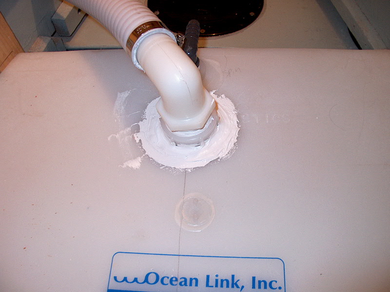
Next, I installed the new fittings I had
purchased. I wrapped the threads with Teflon tape and screwed in the
fittings aligning each one approximately the way I thought the hose might end up
running. Now, on to the hoses--my absolute favorite part, since sanitation
hose is so fun to work with. (Not!)
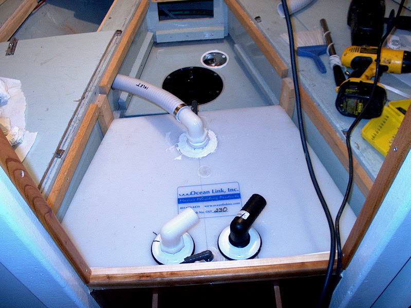 When
I originally installed the toilet last year, I ran a hose forward to beneath the
vee berth, anticipating the installation of a holding tank. With this hose
already in place, my inlet line work was nearly done. To complete the
inlet, I drilled a 2" hole through the vee berth bulkhead near the inlet
fitting on the tank (the most forward fitting). Then, I wrestled the hose
through the hole and marked it for length. Using my inexpensive pull saw,
I cut the hose to length. With a hair dryer, I heated the hose
up a little, and, with effort, got it onto the nipple. Of course, in doing
so I managed to partially break loose the plastic-welded fitting from the
tank. D'OH! The inside of the yacht echoed with epithets. See,
manipulating this stiff, unbendable hose onto a hose nipple requires a bit of
back and forth motion, grunting, and--let's face it--forcing it into
place. This When
I originally installed the toilet last year, I ran a hose forward to beneath the
vee berth, anticipating the installation of a holding tank. With this hose
already in place, my inlet line work was nearly done. To complete the
inlet, I drilled a 2" hole through the vee berth bulkhead near the inlet
fitting on the tank (the most forward fitting). Then, I wrestled the hose
through the hole and marked it for length. Using my inexpensive pull saw,
I cut the hose to length. With a hair dryer, I heated the hose
up a little, and, with effort, got it onto the nipple. Of course, in doing
so I managed to partially break loose the plastic-welded fitting from the
tank. D'OH! The inside of the yacht echoed with epithets. See,
manipulating this stiff, unbendable hose onto a hose nipple requires a bit of
back and forth motion, grunting, and--let's face it--forcing it into
place. This  had
broken the plastic weld. To fix it, I glued it back in place with some 3M
101 that I had around for another project. I forced it into the gap, and
gooped it all around for good measure. I was not pleased with this turn of
events, nor particularly with my fix. Time will tell how effective my
repair is. I secured the hose in place with an AWAB hose clamp. had
broken the plastic weld. To fix it, I glued it back in place with some 3M
101 that I had around for another project. I forced it into the gap, and
gooped it all around for good measure. I was not pleased with this turn of
events, nor particularly with my fix. Time will tell how effective my
repair is. I secured the hose in place with an AWAB hose clamp.
|
|
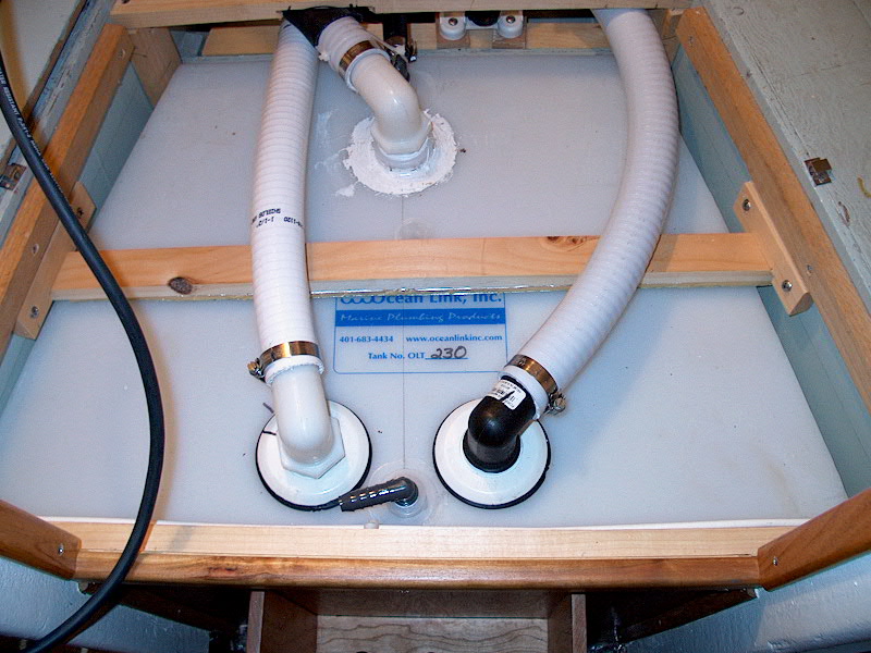
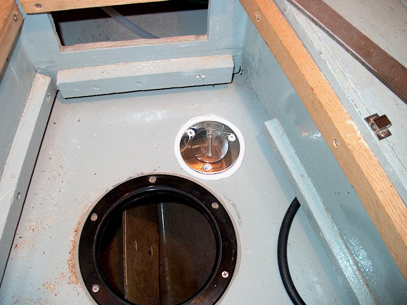 Next,
I had to make a small modification to the water tank. The Triton, as
delivered, did not have a deck fill pipe for the water tank. This is
inconvenient. Last year, I filled the tank by running a hose into the
large inspection port in the tank that I installed. Less than
perfect. My sanitation plans call for a manual waste pump to be located
just forward of the holding tank, on a platform over the existing water
tank. This will make access to the tank even less convenient (though still
possible if necessary), so I thought I would take a moment and address the
issue. I discovered that the 1-1/2" PVC threaded fittings that came
with my holding tank fit perfectly into the threads of a standard waste deck
pipe. So, I drilled a hole in the tank and installed one of these in a
thick bed of 3M 101, holding it in place with screws. I installed the
regular cover for now; later, I'll remove the cap and install one of the pipe
elbows, which will allow me to connect a hose that will run to a deck fitting. Next,
I had to make a small modification to the water tank. The Triton, as
delivered, did not have a deck fill pipe for the water tank. This is
inconvenient. Last year, I filled the tank by running a hose into the
large inspection port in the tank that I installed. Less than
perfect. My sanitation plans call for a manual waste pump to be located
just forward of the holding tank, on a platform over the existing water
tank. This will make access to the tank even less convenient (though still
possible if necessary), so I thought I would take a moment and address the
issue. I discovered that the 1-1/2" PVC threaded fittings that came
with my holding tank fit perfectly into the threads of a standard waste deck
pipe. So, I drilled a hole in the tank and installed one of these in a
thick bed of 3M 101, holding it in place with screws. I installed the
regular cover for now; later, I'll remove the cap and install one of the pipe
elbows, which will allow me to connect a hose that will run to a deck fitting.
 With
that little project out of the way, I built a simple platform--well, two
supports, really--for the Henderson MK V manual waste pump (identical to the one
that we use to pump the head) that we'll use to pump the tank overboard in
appropriate areas. This setup was a requirement for me, since I don't want
to be at the mercy of unavailable or inoperable shoreside pumpout stations to pump
the tank. Our setup will allow us to pump it overboard. I determined
that, in order for the v-berth filler piece to clear the top of the pump, I had
to install it so that the base was even with the old supports for the little
seat that was once installed over the water tank. I cut a couple
1-1/2" strips of wood to fit, and screwed them in place. Simple. With
that little project out of the way, I built a simple platform--well, two
supports, really--for the Henderson MK V manual waste pump (identical to the one
that we use to pump the head) that we'll use to pump the tank overboard in
appropriate areas. This setup was a requirement for me, since I don't want
to be at the mercy of unavailable or inoperable shoreside pumpout stations to pump
the tank. Our setup will allow us to pump it overboard. I determined
that, in order for the v-berth filler piece to clear the top of the pump, I had
to install it so that the base was even with the old supports for the little
seat that was once installed over the water tank. I cut a couple
1-1/2" strips of wood to fit, and screwed them in place. Simple.
|
|
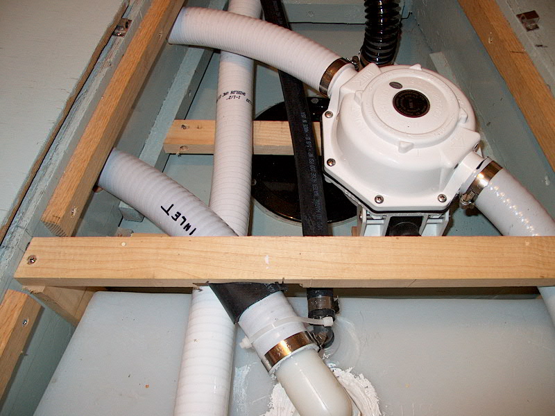
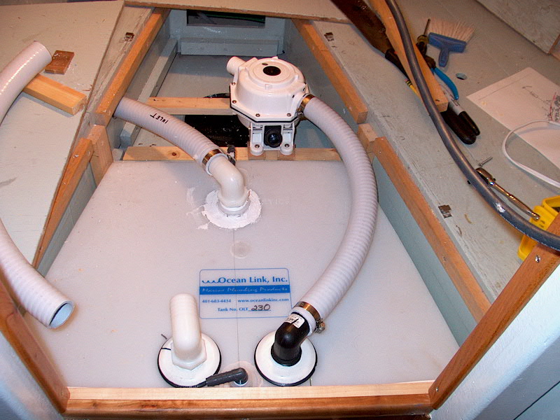 Next,
I installed the waste pump, after changing the alignment of the
intake/discharge. These pumps are great, because you can change the angle
of intake/discharge by removing the eight screws on the top and rotating the
whole casing. With a test piece of hose, I determined the best location
and angle for the pump, and installed it with large screws. I put
some small wedged beneath the after two mounts to raise that part of the pump up
just a bit so that the handle would better clear the front of the holding
tank. When the pump was in place, I cut to fit and installed another
length of sanitation hose, clamping it securely in place at each end. Next,
I installed the waste pump, after changing the alignment of the
intake/discharge. These pumps are great, because you can change the angle
of intake/discharge by removing the eight screws on the top and rotating the
whole casing. With a test piece of hose, I determined the best location
and angle for the pump, and installed it with large screws. I put
some small wedged beneath the after two mounts to raise that part of the pump up
just a bit so that the handle would better clear the front of the holding
tank. When the pump was in place, I cut to fit and installed another
length of sanitation hose, clamping it securely in place at each end.
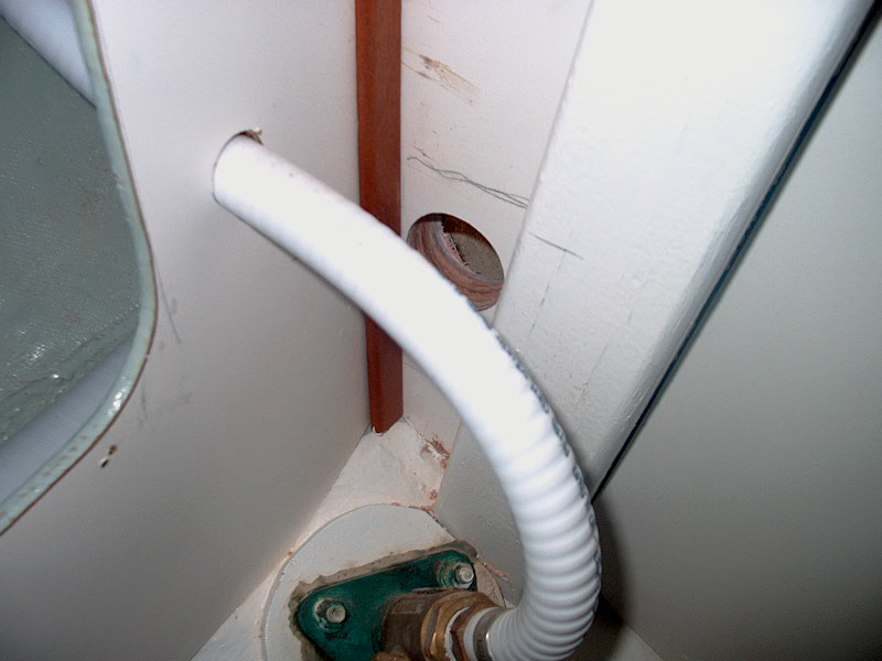
Now the fun really began. The outlet
from the waste pump has to run back aft, beneath the vee berth, exiting
somewhere in the head, where it has to connect with a second Y-valve to that
that the holding tank can be discharged overboard when appropriate. This
project started out OK, once I figured out where to run the hose through the
bulkhead. Ideally, I wanted it hidden, like my original hose (running from
the discharge Y-valve up to the tank inlet). However, there simply wasn't
enough room in the locker behind the head to run another hose--the V-berth
platform is just too low. The next best thing was to drill  a
hole down low in the narrow section between the outboardmost mast beam support
and the longitudinal bulkhead that forms the locker behind the head.
Fortunately, there was enough room down there to fit my big drill with the
2" hole saw. I double checked that I was definitely below the level
of the berth, and drilled away. Success! a
hole down low in the narrow section between the outboardmost mast beam support
and the longitudinal bulkhead that forms the locker behind the head.
Fortunately, there was enough room down there to fit my big drill with the
2" hole saw. I double checked that I was definitely below the level
of the berth, and drilled away. Success!
|
|
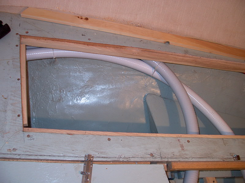
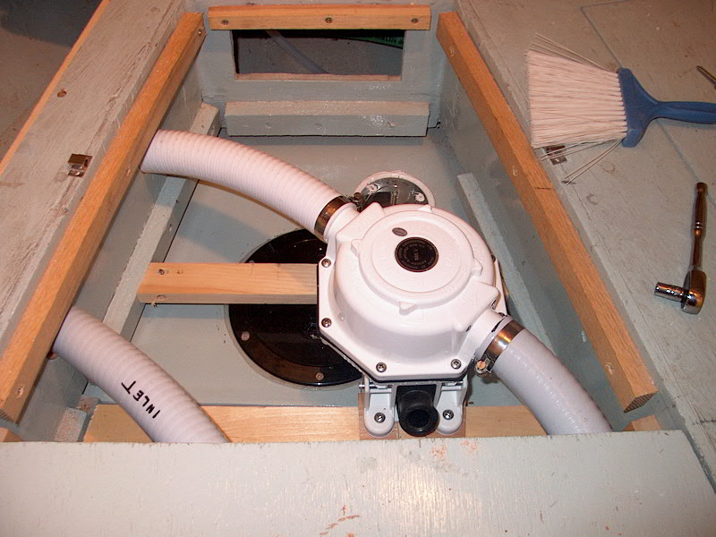 Next,
I ran a long length of hose (starting from the head side) through the new hole
and into the locker beneath the vee berth. Once I determined its ultimate
path and best curvature to reach the outlet side of the waste pump, I drilled
another hole into the center section under the vee berth and ran the hose
through, connecting it to the pump outlet. That wasn't too bad,
right? I used some wire ties to secure the two hoses (inlet and pumpout)
together in the locker under the vee berth. Next,
I ran a long length of hose (starting from the head side) through the new hole
and into the locker beneath the vee berth. Once I determined its ultimate
path and best curvature to reach the outlet side of the waste pump, I drilled
another hole into the center section under the vee berth and ran the hose
through, connecting it to the pump outlet. That wasn't too bad,
right? I used some wire ties to secure the two hoses (inlet and pumpout)
together in the locker under the vee berth.

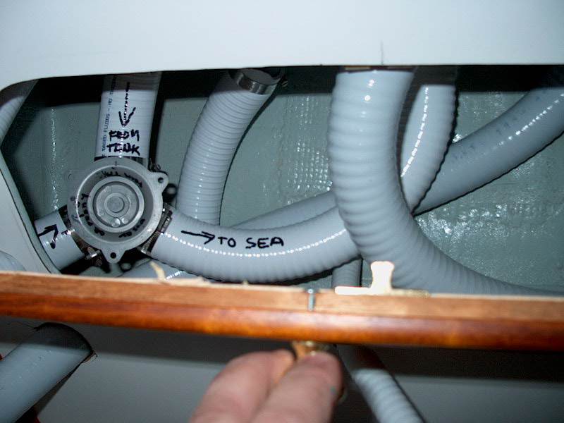
But that was only the easy part. The
tricky part is the final connections in the head. It's only tricky because
of the limited space available (trying to keep the hoses look halfway decent),
and because of the absolutely inflexible, stubborn nature of the white
sanitation hose. It will not make anything approaching a tight curve, and
is really not fun to work with. Please refer to my lousy schematic
on the previous page to refresh your memory, if necessary, to what I am trying
to accomplish with my system. To complete the setup, I need to modify the
existing hoses in the head. What used to be the direct overboard discharge
for the head (running from Y-valve #1 to the seacock) will now have to run to a
second, new Y-valve (#2). A further hose from the other side of Y-valve #2
will continue on to the seacock. The new hose running from the waste pump
by the holding tank will connect to the other leg of #2, allowing it to be
pumped overboard.
|
|
 I attempted several different configurations,
trying to get the hoses to bend and align the way I wanted, but didn't end up
with anything that worked. I'd like to avoid a ridiculous sea of cluttered
hoses, so some means of keeping them neat and organized is my goal. Plus,
I have to work within the limitations of the space available (not much) and the
bending qualities of the hose, such as they are. After a few tries,
I gave
up for the day--I needed the mental and physical break. I attempted several different configurations,
trying to get the hoses to bend and align the way I wanted, but didn't end up
with anything that worked. I'd like to avoid a ridiculous sea of cluttered
hoses, so some means of keeping them neat and organized is my goal. Plus,
I have to work within the limitations of the space available (not much) and the
bending qualities of the hose, such as they are. After a few tries,
I gave
up for the day--I needed the mental and physical break.
|
|
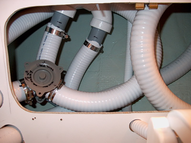
 The next day, I approached the
hoses with a fresh attitude. Using a couple spare pieces of hose as a
mockup, I tried to see how the Y-valve would work inside the locker behind the
head (the so-called "hamper"). I could see that it looked
feasible. I plunged ahead by drilling a hole in the bulkhead aft of the
"hamper" opening for the hose running from the #1 Y-valve to the #2
valve. (I had previously marked the outline of my caned door on the Formica, so
I knew that my holes were outside the area the door covers.) Then, I
drilled two more holes--one above the first one, and one down behind the
toilet--for the other two hoses that need to be run. The next day, I approached the
hoses with a fresh attitude. Using a couple spare pieces of hose as a
mockup, I tried to see how the Y-valve would work inside the locker behind the
head (the so-called "hamper"). I could see that it looked
feasible. I plunged ahead by drilling a hole in the bulkhead aft of the
"hamper" opening for the hose running from the #1 Y-valve to the #2
valve. (I had previously marked the outline of my caned door on the Formica, so
I knew that my holes were outside the area the door covers.) Then, I
drilled two more holes--one above the first one, and one down behind the
toilet--for the other two hoses that need to be run.
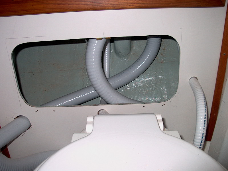
Next, cutting the long hose from
the holding tank roughly to the proper length, I stuffed it through the hole
behind the head, and used the cut portion of the to run through the upper hole
on the other side. I was able to (more or less) easily connect two of the
hoses to the Y-valve, even though the valve ended up upside down in order to get
things to align properly. But I had a problem with the third hose--the one
coming from the holding tank. I couldn't get it to bend so that it would
meet up with the nipple on the Y-valve, and when I finally forced it into
position, the hose kinked because the radius was too tight. However, I
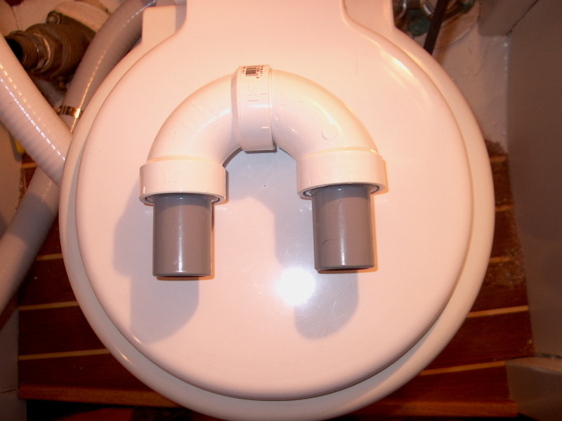
decided I liked the general setup and, since I had some PVC elbows and rigid
PVC-hose adapters that came with the holding tank, I thought I could replace the
kinked section of hose with a nice  PVC 180° bend. I had to go to
the hardware store for glue and a second PVC elbow with two female sides in
order to make it work. I glued up the arrangement and cut the kinked part
of the hose out. Cool, thought I...soon, the running of the hoses would be
over, as it would surely be pretty easy to slip the last piece into place. PVC 180° bend. I had to go to
the hardware store for glue and a second PVC elbow with two female sides in
order to make it work. I glued up the arrangement and cut the kinked part
of the hose out. Cool, thought I...soon, the running of the hoses would be
over, as it would surely be pretty easy to slip the last piece into place.
|
| Wrong. I don't know what
the deal is, but those smooth gray PVC-hose adapters sure don't fit into the
hose! Heating the hose basically made matters worse instead of better, as
the hose then extended to stick to the fittings. Cold hose was an
impossibility too. I spent way too long trying to get this thing into
place, becoming far too intimate with the toilet in the process. After
what seemed like hours of struggle, I had the hose maybe 1/8" onto the
fittings--not enough to clamp yet. Aaarrrrrgh! I gave up for the
day, leaving things as they were. So close to success...but still so
far. Nothing I had tried had made me able to get the hose more onto the
fittings--a problem compounded by the tight access inside the locker. What
a pain. Frustrated, tired, and angry, I quit for the day. |
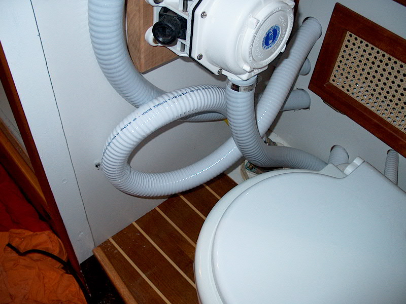
 After
a couple days' respite, I returned to fight my white whale. With much
grunting, groaning and physical effort and contortion, I was finally able to get
the two hoses onto the fittings enough to satisfy me, and to provide enough
surface to clamp properly. What a miserable chore. If I never see
another piece of white sanitation hose again, it'll be too soon. With the
final pieces clamped in place, I secured the one remaining end to the bronze
overboard discharge After
a couple days' respite, I returned to fight my white whale. With much
grunting, groaning and physical effort and contortion, I was finally able to get
the two hoses onto the fittings enough to satisfy me, and to provide enough
surface to clamp properly. What a miserable chore. If I never see
another piece of white sanitation hose again, it'll be too soon. With the
final pieces clamped in place, I secured the one remaining end to the bronze
overboard discharge  seacock.
I used a plastic wire tie to pull and hold
the discharge loop hose into the bulkhead to keep it out of the way. seacock.
I used a plastic wire tie to pull and hold
the discharge loop hose into the bulkhead to keep it out of the way.
|
|
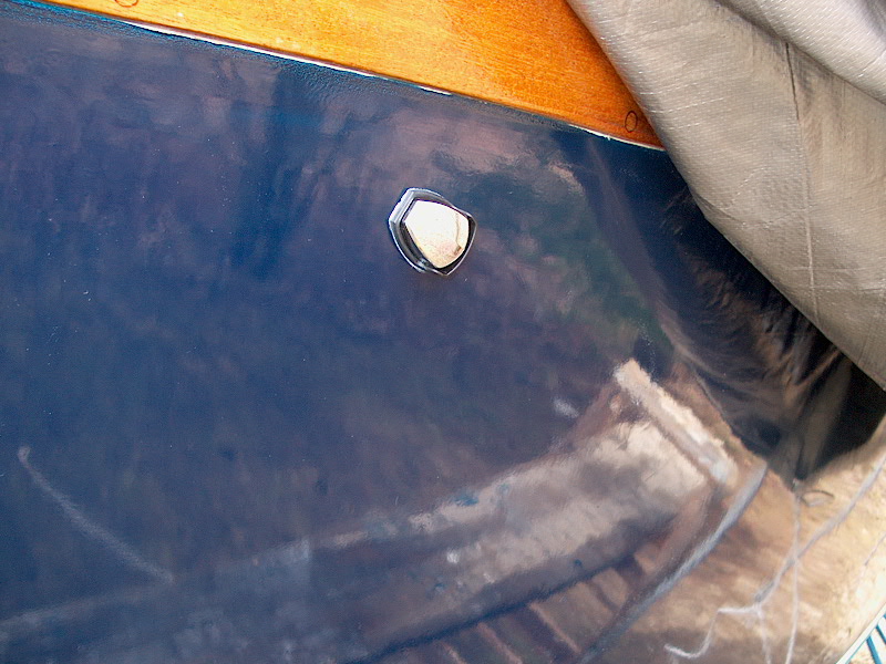
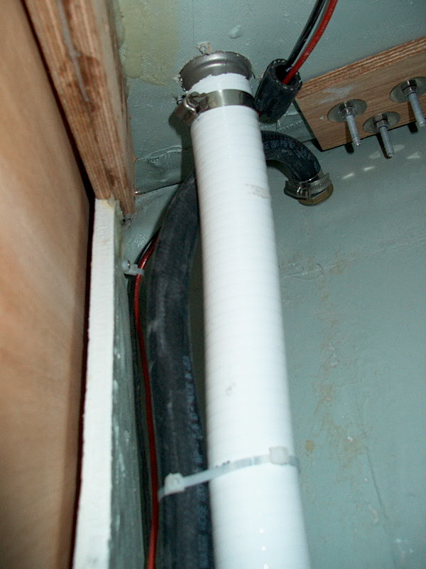
 I ran a 5/8" hose from the
forward vent fitting up into the chain locker. To terminate the vent, I
added a through hull vent fitting in the hull on the port side, up near the
toerail and about three feet back from the stem. I chose this location
because (1.) it is accessible from the inside for hose attachment and (2.)
a location near the bow is desirable so that the vent fitting does not
continually go under water every time the boat heels. Except for the
transom, there's really no where on the boat to put the vent where it will never
be under water, if only for a short time, and running a vent line from the
forward holding tank to the transom would be inefficient, difficult, and
possibly ineffective. The fitting I chose features a little plastic shield
that will prevent most splash-type water from getting inside. I ran a 5/8" hose from the
forward vent fitting up into the chain locker. To terminate the vent, I
added a through hull vent fitting in the hull on the port side, up near the
toerail and about three feet back from the stem. I chose this location
because (1.) it is accessible from the inside for hose attachment and (2.)
a location near the bow is desirable so that the vent fitting does not
continually go under water every time the boat heels. Except for the
transom, there's really no where on the boat to put the vent where it will never
be under water, if only for a short time, and running a vent line from the
forward holding tank to the transom would be inefficient, difficult, and
possibly ineffective. The fitting I chose features a little plastic shield
that will prevent most splash-type water from getting inside.
|
|
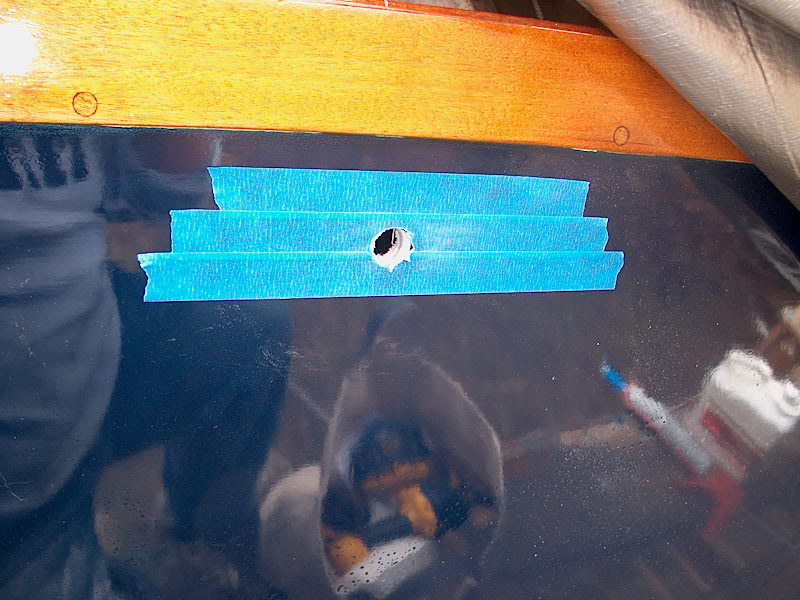
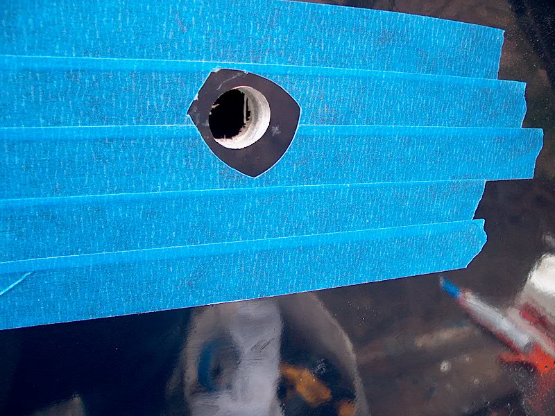
 From
inside the chain locker, I drilled a small pilot hole to mark the location on
the outside. Once outside the boat, I taped over the area to be drilled
(to help prevent chipping) and, with great trepidation, began drilling the
hole. The vent required a 3/4" hole, and the only bit I have in
that size is a spade bit--notorious for walking out of the hole at the
start. Carefully, I applied pressure and drilled into the hull.
Success--no chipping whatsoever! The hull is a satisfying 5/8" thick
at this level; as many times as I "discover" the thickness of this
hull, I still never From
inside the chain locker, I drilled a small pilot hole to mark the location on
the outside. Once outside the boat, I taped over the area to be drilled
(to help prevent chipping) and, with great trepidation, began drilling the
hole. The vent required a 3/4" hole, and the only bit I have in
that size is a spade bit--notorious for walking out of the hole at the
start. Carefully, I applied pressure and drilled into the hull.
Success--no chipping whatsoever! The hull is a satisfying 5/8" thick
at this level; as many times as I "discover" the thickness of this
hull, I still never  cease
to be amazed and impressed by it. With the hole drilled, I applied a
little more tape on the hull and scribed around the vent fitting with a utility
knife, then removed the tape inside the line, where the fitting will sit.
This will prevent caulk from oozing everywhere. cease
to be amazed and impressed by it. With the hole drilled, I applied a
little more tape on the hull and scribed around the vent fitting with a utility
knife, then removed the tape inside the line, where the fitting will sit.
This will prevent caulk from oozing everywhere.
|
|
 With that done, I applied a bead
of polysulfide to the back of the vent fitting and pressed it into place.
I carefully taped in in place to hold it while I went inside to install the
plastic washer and bronze nut that hold it in place. I held the nipple on
the inside while I tightened the nut to keep the vent fitting from With that done, I applied a bead
of polysulfide to the back of the vent fitting and pressed it into place.
I carefully taped in in place to hold it while I went inside to install the
plastic washer and bronze nut that hold it in place. I held the nipple on
the inside while I tightened the nut to keep the vent fitting from  twisting.
When the nut was tight, I went outside, slightly straightened the fitting, and
cleaned up the excess caulk that had squeezed out. Then I removed the
tape. I attached the hose to the nipple on the inside and clamped it in
place. twisting.
When the nut was tight, I went outside, slightly straightened the fitting, and
cleaned up the excess caulk that had squeezed out. Then I removed the
tape. I attached the hose to the nipple on the inside and clamped it in
place.
I installed a bronze plug in the
second vent opening for now; we'll see how it goes.
I know that Peggie Hall recommends two vents, which is why I spec'd the tank
that way, but if I don't need the second vent, I'd prefer to avoid installing
it. Time will tell.
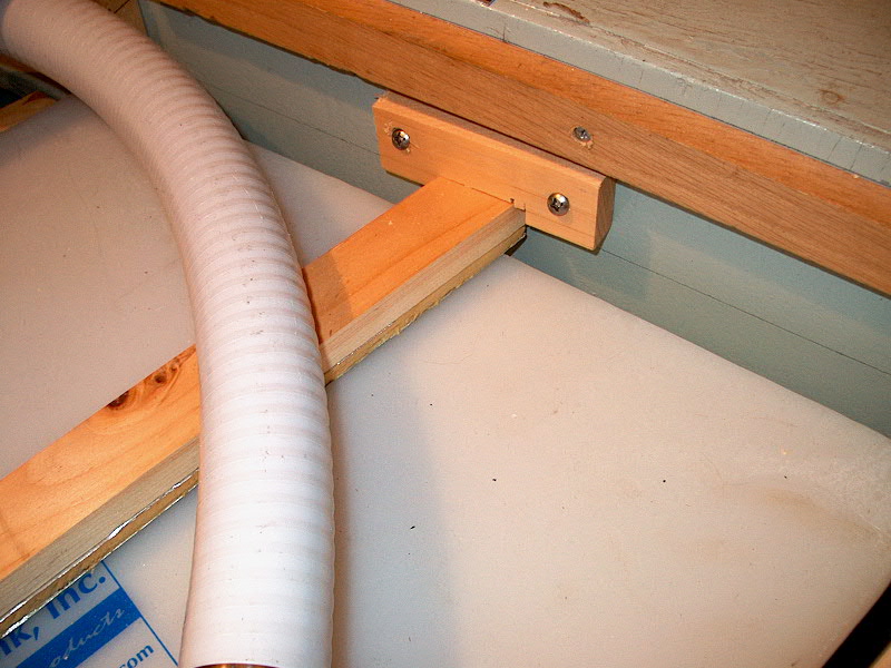
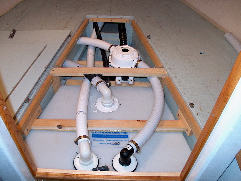
 The hoses and such attached to
the tank are stiff enough, and the fit of the tank close enough, that movement
of the tank seems unlikely under the types of conditions we expect to sail
in. However, to add a little insurance, I installed a wooden cleat over
the center of the tank, padded with some leftover foam from the icebox
project. I secured the cleat to the sides of the vee berth cutout with
some simple wooden brackets. The hoses and such attached to
the tank are stiff enough, and the fit of the tank close enough, that movement
of the tank seems unlikely under the types of conditions we expect to sail
in. However, to add a little insurance, I installed a wooden cleat over
the center of the tank, padded with some leftover foam from the icebox
project. I secured the cleat to the sides of the vee berth cutout with
some simple wooden brackets.

|
|
Finally, I ran one more length of
white hose from the second dip tube connection on the tank beneath the vee berth
up forward to the chain locker, where it is secured to a new waste
pipe deck fitting on the foredeck.
|
|