|
The Head:
Page 2
This page was last updated on 6 March 2002
Return to Head Page 1
|
|
Installing
the Lavac Popular
Marine
Toilet
I finally ordered a
toilet for the head, after putting it off for months. I ordered a Lavac
Popular from Defender, after much thought. While I have no direct
experience with these vacuum-flush heads, I have heard only good things, and the
simple design seems almost too good to be true. Struggling with a marine
toilet is not one of the things I plan on spending my cruises doing!
Besides, they come highly recommended by James Baldwin of Atom
fame. The toilet is currently on order; Ill post details of the installation
later on.
I copped out on the
holding tank for now. (See below for an update.) There is just so much to do, and I can't
bother myself worrying about the best holding tank installation.
Therefore, I ordered one of the flexible bladder tanks, which I have heard
nothing good about, but for now, at least, it will meet applicable 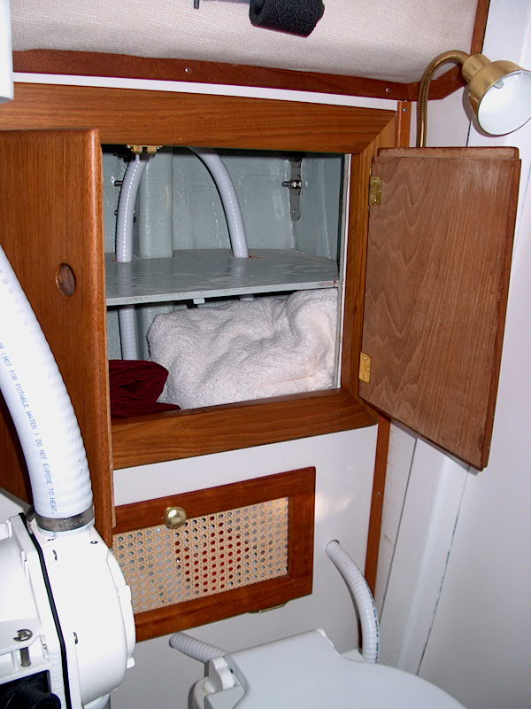 regulations,
which is all I care about at this point. I expect to replace the tank and
reengineer the whole system in the future, but not right now. There's no
time to reinvent the wheel. regulations,
which is all I care about at this point. I expect to replace the tank and
reengineer the whole system in the future, but not right now. There's no
time to reinvent the wheel.
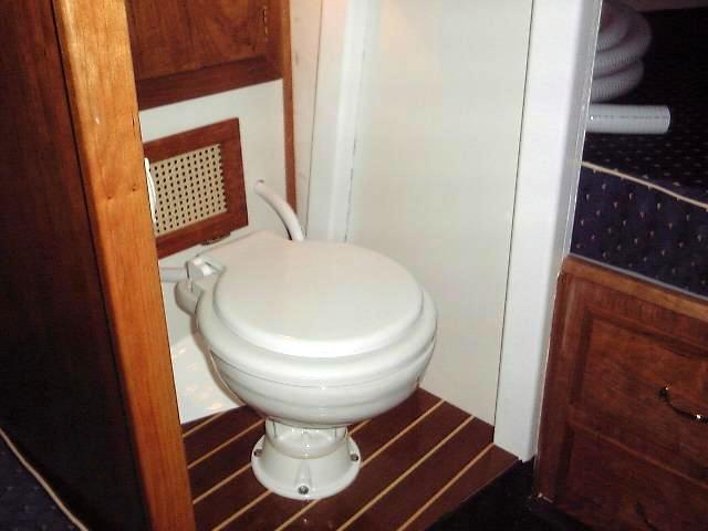
I
installed the toilet with four lag screws and silicone. It's a nice, clean
installation, with plenty of room remaining. Once the unit was screwed
down, I moved on to the hoses. I used white sanitation hose for intake and
discharge--it is awful stuff to work with, as it is very stiff and hard.
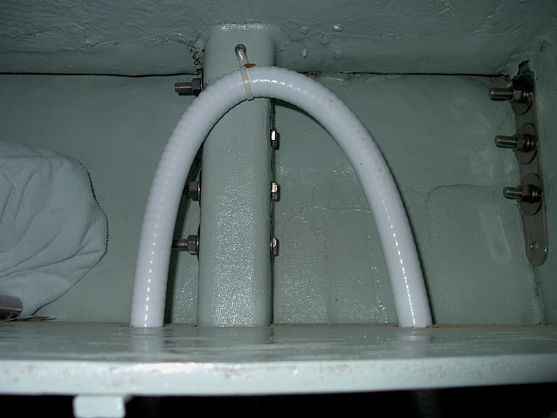
The intake line runs from the seacock, through the bulkhead, and into a high
loop inside the cabinet, then back down inside and emerges just behind the
toilet. This is a required feature of the Lavac, and there is a special
air vent that is installed in the top of the loop. (Click the thumbnail below)

|
|
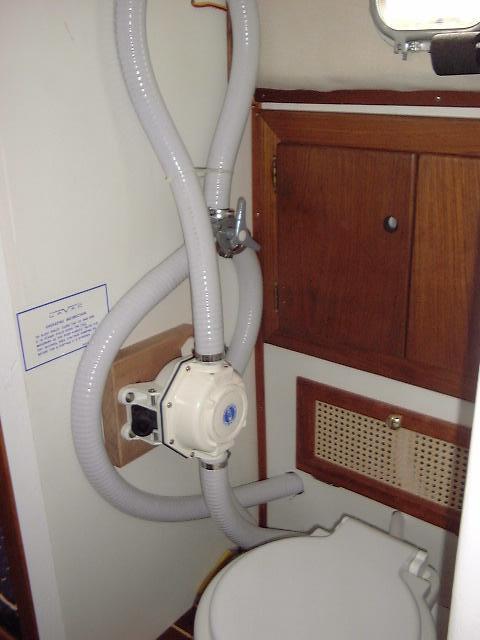 I had hoped to run
the discharge hoses inside the locker as well, but upon reading the installation
instructions for the included Henderson pump, I noted that I had to mount the
pump vertically--I had hoped to mount it on the platform next to the
toilet. I ended up mounting it on the aft bulkhead, which keeps the hoses
hidden from view when in the salon. The discharge from the toilet runs up
to the bottom side of the pump, then above the pump into a high loop before
returning down to the Y-valve, which I installed next to the pump. From
the valve, one hose leads to the overboard discharge; the other snakes around
and disappears inside the locker before running forward to beneath the port vee
berth, where the holding tank will soon be installed. I tried to keep the
hoses as neat and unobtrusive as possible--but there was no avoiding having them
exposed for my particular installation. I had hoped to run
the discharge hoses inside the locker as well, but upon reading the installation
instructions for the included Henderson pump, I noted that I had to mount the
pump vertically--I had hoped to mount it on the platform next to the
toilet. I ended up mounting it on the aft bulkhead, which keeps the hoses
hidden from view when in the salon. The discharge from the toilet runs up
to the bottom side of the pump, then above the pump into a high loop before
returning down to the Y-valve, which I installed next to the pump. From
the valve, one hose leads to the overboard discharge; the other snakes around
and disappears inside the locker before running forward to beneath the port vee
berth, where the holding tank will soon be installed. I tried to keep the
hoses as neat and unobtrusive as possible--but there was no avoiding having them
exposed for my particular installation.
|
|
 I tested the head
once the boat was in the water. What a neat system...except for the fact
that, from the factory, the bolts securing the toilet bowl to the base, which
joint is sealed with a gasket, were not tightened, so water leaked all
over. I had to remove the toilet from the sole and tighten the four bolts,
which took care of the problem but was an unnecessary annoyance. And boy, does that vacuum seal the
lids--it takes 10 seconds or longer after pumping to be able to pry the lid back
up. I tested the head
once the boat was in the water. What a neat system...except for the fact
that, from the factory, the bolts securing the toilet bowl to the base, which
joint is sealed with a gasket, were not tightened, so water leaked all
over. I had to remove the toilet from the sole and tighten the four bolts,
which took care of the problem but was an unnecessary annoyance. And boy, does that vacuum seal the
lids--it takes 10 seconds or longer after pumping to be able to pry the lid back
up.
After a season of
use, we are very pleased with the head. The one thing that we learned was
that sometimes the lid or seat might be a little cocked out of position, so the
seals wouldn't allow the vacuum to form properly. This led to some long
pumping sessions while trying to figure out why it wasn't working
properly. Once this very minor problem--and the solution (make sure the
seat and lid are properly aligned before beginning the pumping cycle)--became
apparent, we experienced absolutely no problems with head performance.
|
|
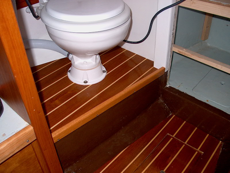 The
platform on which the head is installed required a piece of trim on the outside
to cover the edge of the plywood sole. I milled a piece out of mahogany to
match the other head trim and installed it with screws after finishing with tung
oil. The
platform on which the head is installed required a piece of trim on the outside
to cover the edge of the plywood sole. I milled a piece out of mahogany to
match the other head trim and installed it with screws after finishing with tung
oil.
|
|
Holding
Tank
My original plan had been to
cram a Nauta flexible holding tank into the tiny space beneath the vee berth
forward of the head. Sailing and enjoying the boat prevented me from
getting into this project during the 2001 season, but once we hauled the
boat for the winter I knew that I had to come up with a solid, workable solution
to the containment problem. The flexible tank seemed to be out--too
impractical for actual use. It seemed the only solution was to put a tank
in the space in the center of the vee berth. This would mean giving up the
nice drawers that I installed there, but I
think having a decent, large, practical holding tank has to win this war.
We can find other storage space to make up for the lost drawers, but there's
really nowhere else for a good-sized holding tank.
My plan for the waste system
is to allow both containment and direct overboard discharge, and to make it easy
to switch between the two as necessary. I will also install an effective
means of emptying the tank directly overboard when it's possible to do so, as
well as to have an on-deck pumpout for shoreside facilities. No matter how
I plan it out, it ends up more complicated than I would like, but there's just
no other way. We certainly can't rely on shoreside pumpout
facilities--they range anywhere from nonexistent to non-functional to horribly
inconvenient at best. I also want to minimize clutter and complicated hose
and valve runs.
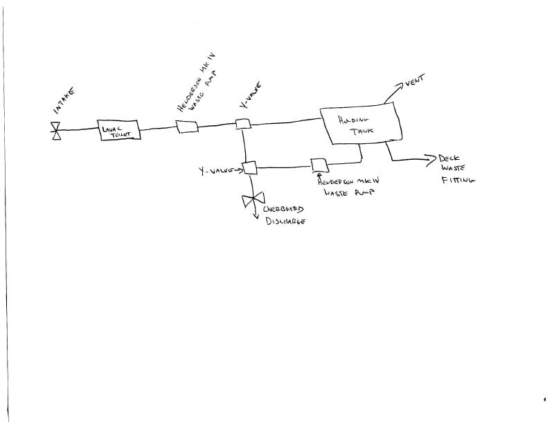
 What
I have come up with is best described with this really crude diagram I put
together. (Please click on the thumbnail for full size.) A draftsman or
penman I am not, so I apologize for the presentation! However, it gets the
general layout across. From the toilet, the flow runs through a Henderson
MK IV manual waste pump--the one that comes standard with the Lavac
toilet. Next is a Y-valve that allows the flow to be directed to either
the holding tank or directly overboard through the sea valve. From the
holding tank, there are three outlets: a vent line, a hose that will run
to a deck fitting for pumpout, and a final hose that runs from the tank, through
a second Henderson MK IV waste pump, and to a second Y-valve installed in the
discharge line between the first Y-valve and the overboard
discharge. What
I have come up with is best described with this really crude diagram I put
together. (Please click on the thumbnail for full size.) A draftsman or
penman I am not, so I apologize for the presentation! However, it gets the
general layout across. From the toilet, the flow runs through a Henderson
MK IV manual waste pump--the one that comes standard with the Lavac
toilet. Next is a Y-valve that allows the flow to be directed to either
the holding tank or directly overboard through the sea valve. From the
holding tank, there are three outlets: a vent line, a hose that will run
to a deck fitting for pumpout, and a final hose that runs from the tank, through
a second Henderson MK IV waste pump, and to a second Y-valve installed in the
discharge line between the first Y-valve and the overboard
discharge.
|
|
 Thanks
to a friend, I found a polyethylene holding tank that looks perfect for the
space available between the V berth. The tank is built by Ocean
Link Inc. in Rhode Island, and looks to be of high quality--3/8"
minimum wall thickness to prevent permeation. The tank is # OLT-230
(right). Note that this drawing does not show the exact shape of all
profiles of the tank, but the dimensions are accurate. I also found a tank
of identical dimensions at Ronco Plastics.
Ronco's drawing fills in a couple details that this drawing (right) misses, so
it's worth taking a look at. What I haven't figured out yet is if the
construction is the same. Ronco's tank (# B115) is somewhat less
expensive, but I fear it may have thinner walls. I will definitely go with
the thickest walls, but if the two tanks are constructed the same, I will choose
the less expensive one. Research is underway at this time. Thanks
to a friend, I found a polyethylene holding tank that looks perfect for the
space available between the V berth. The tank is built by Ocean
Link Inc. in Rhode Island, and looks to be of high quality--3/8"
minimum wall thickness to prevent permeation. The tank is # OLT-230
(right). Note that this drawing does not show the exact shape of all
profiles of the tank, but the dimensions are accurate. I also found a tank
of identical dimensions at Ronco Plastics.
Ronco's drawing fills in a couple details that this drawing (right) misses, so
it's worth taking a look at. What I haven't figured out yet is if the
construction is the same. Ronco's tank (# B115) is somewhat less
expensive, but I fear it may have thinner walls. I will definitely go with
the thickest walls, but if the two tanks are constructed the same, I will choose
the less expensive one. Research is underway at this time.
After seeing Ocean Link's tank
in person, I decided to go ahead with it. I ordered the tank with two dip
tubes for the double discharges, a single inlet, and two vent fittings--along
with the requisite PVC and hose fittings (See below).
Construction of the tank is underway and I expect it in a couple weeks.
The tank was very pricey. I have all the other materials required for the
job on hand.
|
|
Installing the Tank
Before installing the holding
tank, I had to take care of a small issue. The hose connection for the
fresh water tank is normally accessed through the little hatch on the sole of
the vee berth--directly beneath where the holding tank will sit. Now,
removal of the tank in order to replace this water hose every 10 years or so is
OK, but I like to remove it to drain the water tank at the end of the season, or
whenever else it seems necessary. Obviously, this was going to be
impossible once the holding tank was in place.
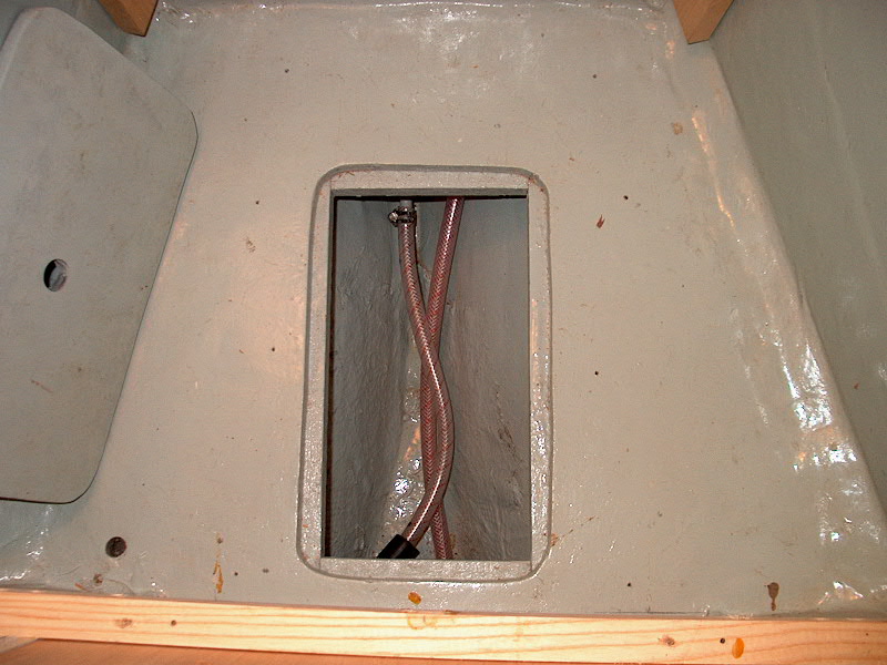 To
get around this, I bought a 3-way diverter valve (bronze) and installed it just
downstream of the tank fitting. I installed it so that I could reach it
from the hatch in the cabin sole in the head. Turning the valve one way
directs the water normally into the supply hose for the two sinks.
Turning it the other way will drain the tank. In the picture, you can't
see the valve--it's below the bottom of the picture. The hose on the left
is the supply from the tank (the tank connection is at the top center of the
opening), and the hose on the right is the water supply line running from the
new valve back up by the tank and through the starboard side of the vee berth to
the head vanity. Because of the tight space in the bilge where
the valve ended up, I had to reverse the handle on the diverter valve. To
get around this, I bought a 3-way diverter valve (bronze) and installed it just
downstream of the tank fitting. I installed it so that I could reach it
from the hatch in the cabin sole in the head. Turning the valve one way
directs the water normally into the supply hose for the two sinks.
Turning it the other way will drain the tank. In the picture, you can't
see the valve--it's below the bottom of the picture. The hose on the left
is the supply from the tank (the tank connection is at the top center of the
opening), and the hose on the right is the water supply line running from the
new valve back up by the tank and through the starboard side of the vee berth to
the head vanity. Because of the tight space in the bilge where
the valve ended up, I had to reverse the handle on the diverter valve.
|
|
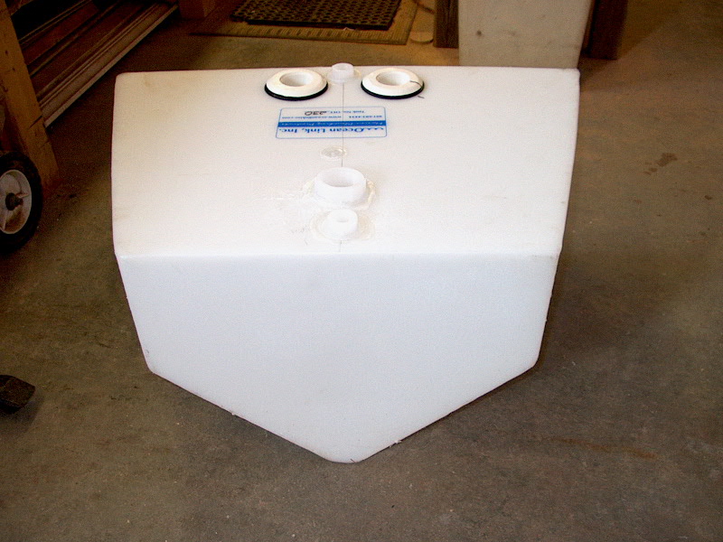
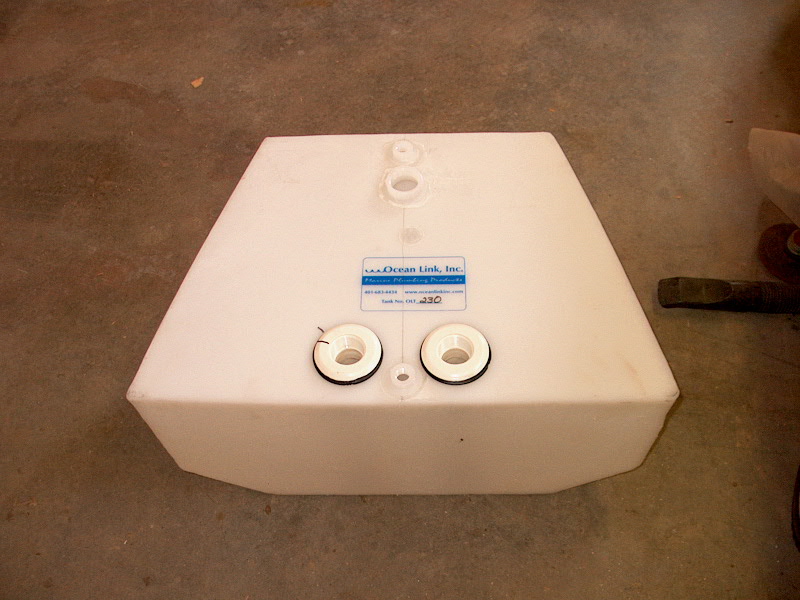
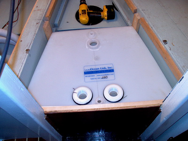
My new tank was delivered
right on schedule. For anyone interested in the OLT-230, here are front,
side, and back pictures of the tank as delivered:


|
|
The two openings at the back
of the tank are the dip tubes for the pump outs. In between them is a vent
fitting. At the forward end is the inlet opening, and a second vent.
They were not able to supply what I really wanted for the hose
connections--simple 90-degree fittings with a hose nipple on one end and threads
on the other. (Read on for more on this.) Therefore, I was talked
into buying a series of PVC elbows, threaded inserts, and special pieces that
insert into the PVC elbow and have a smooth hose fitting on the other end.
I was worried about the clearance above the tank, but went ahead with the order
for these pieces.
 To
get the tank to fit in the opening between the vee berth, I had to remove a
couple of the cleats that were installed to support the vee berth filler
pieces--I had to remove the middle section, and one of the side pieces.
Once I did this, the tank slid in perfectly, with only about 1/2" of
movement possible in a fore and aft direction without the need to add more
braces. I will add some additional braces to prevent the tank from moving
at all a little later in the process. It really is a perfect fit...amazing
that it's a stock tank! To
get the tank to fit in the opening between the vee berth, I had to remove a
couple of the cleats that were installed to support the vee berth filler
pieces--I had to remove the middle section, and one of the side pieces.
Once I did this, the tank slid in perfectly, with only about 1/2" of
movement possible in a fore and aft direction without the need to add more
braces. I will add some additional braces to prevent the tank from moving
at all a little later in the process. It really is a perfect fit...amazing
that it's a stock tank!
When I test-installed one of
the supplied PVC elbows and inserts, of course I found out that they took up too
much vertical space, and the plywood filler piece would not fit over the
top. It was close, and I probably could have routed out a bit of the bottom
of the plywood or something, but no, I had to go on a quest for the 90-degree
fittings I had been looking for at the beginning of the process. I drove
to the hardware store, but they didn't have anything. They have the
straight version, but no elbows. None in the catalog, either. It
never fails that they don't make the fitting I am looking for. I continued
on to West Marine in search of something else. I found two Marelon
tailpieces that were fine--but I needed three. I looked at the selection
for the longest time, but didn't see anything else suitable. Then, I
turned around--and on the other side of the aisle, there were some holding tank
accessories. Among the stuff was a Todd conversion kit that contained two
nylon 1-1/2" elbows that were threaded on one end with a hose nipple on the
other! Bingo! I bought the kit, and one of the Marelon tailpieces to
round out what I needed.
|
|
|
Please
click here to continue the project.
|
|