|
Replacing the Cockpit Scuppers
This page was last updated on 7 January 2004. |
In the spring of 2003, I discovered yet more damage to the flimsy, poorly-designed original
fiberglass scupper tubes beneath the cockpit. At the time, with launch date approaching and a history of distrust over
the condition of the scupper in the first place (meaning that I always kept the seacock closed), I made some temporary
repairs that I hoped would suffice for the season. They did, though I never trusted the arrangement enough to keep the
seacock open. At that time, I vowed to reconfigure the scuppers once the season ended.
Need a refresher? Click here to
revisit the original scuppers and subsequent repairs made. |
During the fall of 2003, I researched some possible solutions to the scupper replacement.
One of the major issues that I faced over the previous years was the tight clearance between the original fiberglass scupper
trees and the seacocks I installed to replace the original solid fiberglass tubes. This tight clearance meant that
many options were unfeasible, and I searched for premanufactured scupper fittings that would fit in the minimal space
involved--and, most importantly, that would allow more successful and easier connection of the stiff reinforced scupper
drain hose required. The options were few, but I finally found what looked to be the perfect fittings at Spartan
Marine. Spartan might be best known as the company that supplied most of the solid bronze deck hardware, ports,
and seacocks for many Cape Dory boats, and happens to be located nearby in Georgetown, ME.
 After
browsing the catalog, I decided to order a set of two different scupper types offered, since I wasn't sure offhand which one
would be a better fit. I figured I would return whichever pair I decided not to use, but that at least I would be able
to physically see the options and make the best choice. The parts arrived within a week of my order, and I prepared to
begin the project. After
browsing the catalog, I decided to order a set of two different scupper types offered, since I wasn't sure offhand which one
would be a better fit. I figured I would return whichever pair I decided not to use, but that at least I would be able
to physically see the options and make the best choice. The parts arrived within a week of my order, and I prepared to
begin the project.
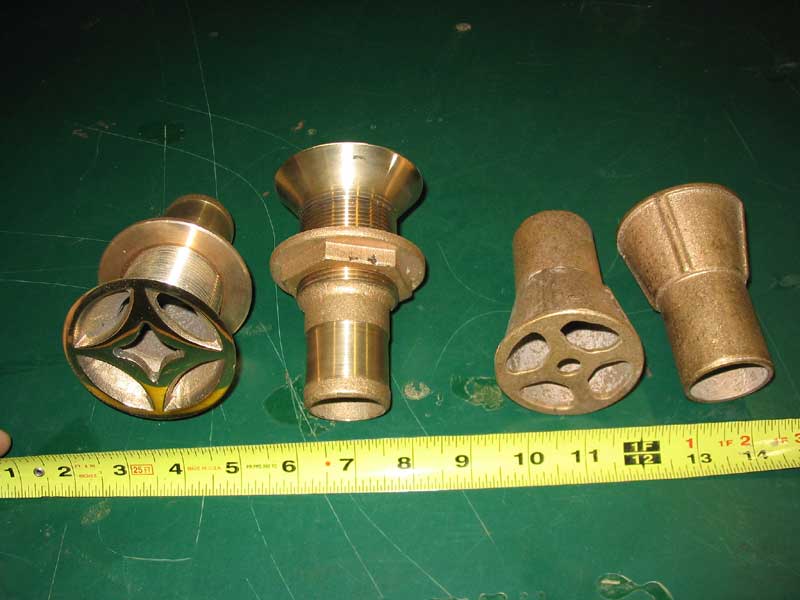
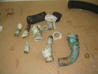
The two sets of scuppers shown are Spartan #255PB, on the left, and #251, on the right.
The 255s are great looking units, but were a bit too large for my application--the flange is too large, and the length a bit
longer than I would like. Spartan offers a mold designed to assist in creating the flush countersink and bevel
required for installing these fittings. |
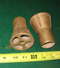 The 251s, however, are close to perfect, and have the added benefit of being 1/3 the cost of
the other units. These are designed to be glassed (epoxied) in place for a permanent, flush, and strong installation. The 251s, however, are close to perfect, and have the added benefit of being 1/3 the cost of
the other units. These are designed to be glassed (epoxied) in place for a permanent, flush, and strong installation.
I purposely held off on beginning the removal of the old scuppers until the new ones arrived,
so that I could assess what kind of a project it would be, and how to proceed. But once I got the new fittings in my
hot little hands, I wasted no time getting going. At first, I questioned how to proceed, and spent some time overnight
thinking over some possible solutions. I wasn't initially sure whether to cut a large hole and fill it in with the
scupper and epoxy mash, or whether I could--or would want to--somehow mill a bevel in the existing fiberglass. I began
the project with no clear direction, other than the fact that I knew I needed to remove the existing fiberglass tubes
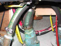
beneath the cockpit corners--the "scupper tree", as I called it.
With two deck drains one each side--one outside of the coamings and one in the cockpit
seat--in addition to the main cockpit drains, each tree was a complex, glassed-together arrangement consisting of various
fiberglass tubes intersecting at appropriate angles directly beneath the cockpit. In this way, the sidedeck drains
could intersect and drain in conjunction with the main scuppers, which I suppose once seemed like a good idea.
Originally, the scuppers were connected directly with the hull below the waterline through fiberglass tubes and short hose
lengths. When I removed the tubes early on during my restoration of the boat some years earlier, I replaced them with
bronze seacocks. But the overall height and mass of the tree beneath the cockpit made for some trick--and nearly
impossible--hose bends in order to connect the scuppers with their new seacocks, and it was inevitable that the whole thing
would require changing at some point.
|
|

|
Removing the Old Scuppers
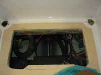
My first step before beginning demolition was to increase access to the scupper locations as much as possible.
Fortunately, access was fair since I had previously installed a large access hatch in the cockpit sole for this and other
purposes. As it happened, I had removed the access hatch a few weeks earlier in preparing for painting the deck
nonskid (and for, as it turned out, upgrading the hatch to a new cast aluminum
version). With the hatch completely out of the way, I had a large access hole directly aft of the scuppers. To
further aid my access, I removed the engine starting and ship's batteries from their locations at the forward ends of the
port and starboard cockpit lockers, respectively. Removing the batteries allowed access from the inside of the locker,
and also was necessary to prevent collateral damage to the batteries or associated wiring. I also removed the
screwed-on debris screens that were over the scupper openings in the cockpit. |
|
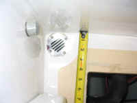
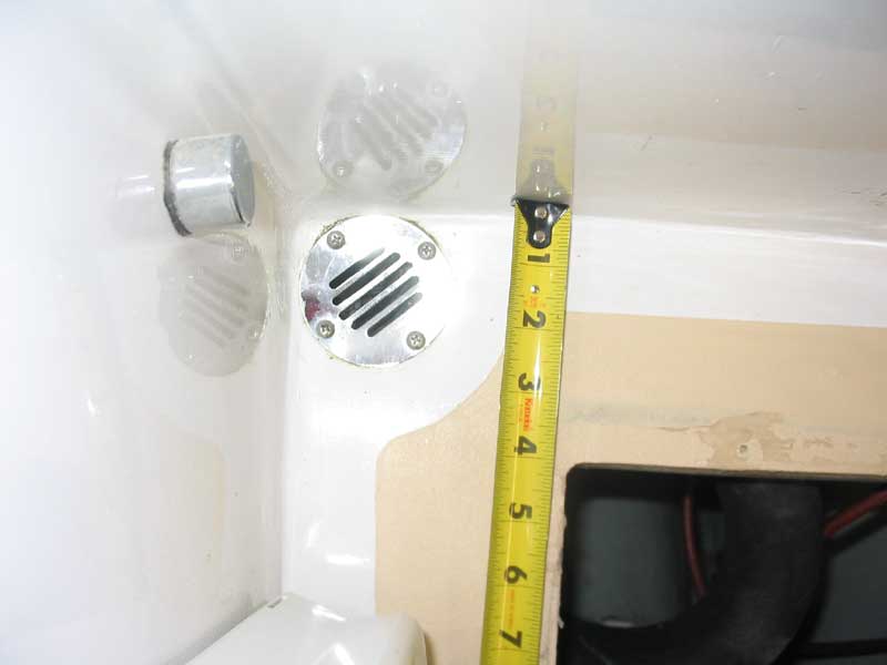
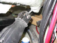
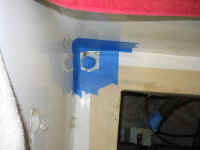
Port scupper before any demolition or removal, showing relative location.
|

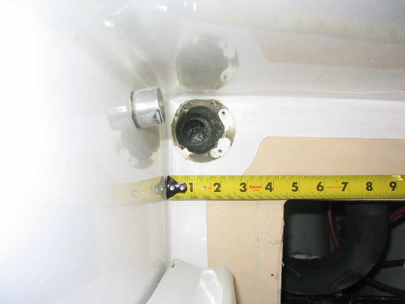
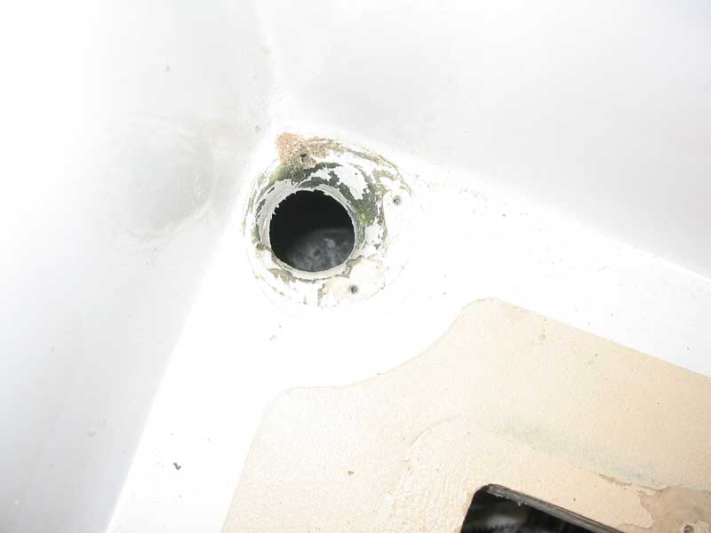
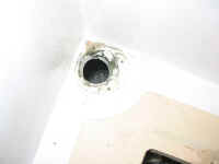
Scupper after removal of the debris screen, showing the true opening. |

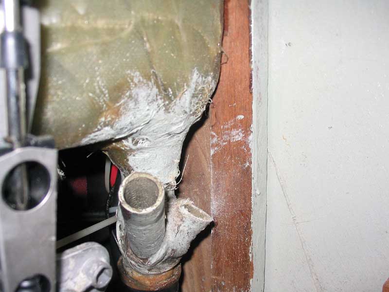
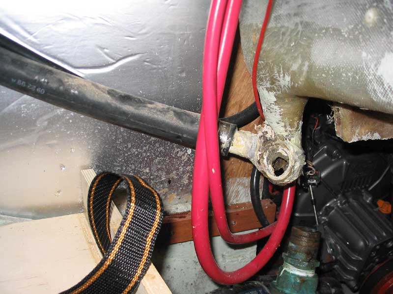
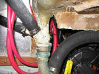
This is how the port scupper looked beneath the cockpit, before the project. |
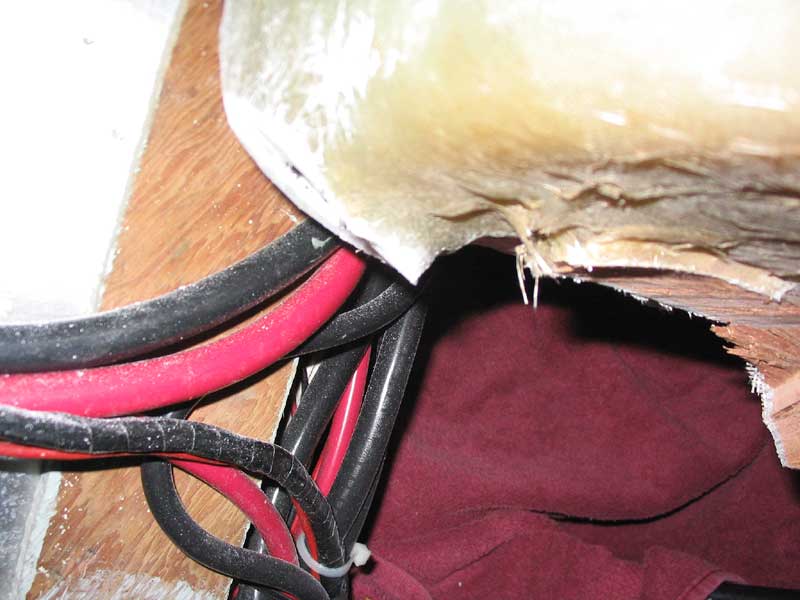
This shows the starboard scupper; this one was in better condition. |
With the debris screens and access hatch removed, I was ready to begin. |
For a time, I stared at the two scuppers from a variety of angles, and tried to determine how
best to proceed. I disconnected the hoses from their various attachment points, and shifted some battery cables and
diesel fuel lines out of the way for protection and to gain access. I found that additional access for inspection and,
as it later turned out, cutting, was possible from inside the cabin through the engine room. My first priority was to
protect the surrounding installations from damage, so I took care to ensure that anything in harms way was removed
first. To catch debris, I spread a towel across the bilge aft of the engine.
Once I had removed--or, in the case of the port side, broken free--the hoses and such, I
attacked the remaining tubes with my reciprocating saw. Cutting the tubes off as closely as possible to the underside
of the cockpit well took two passes with the saw on each tube--the first to cut off the bulk, and the second, usually from a
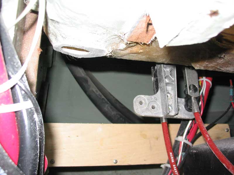
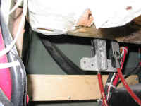
different angle, to cut more closely. For better access now and in the future, I cut away a portion, on each
side, of a glassed-in mahogany transverse brace that was installed near the forward end of the cockpit. |

The port scupper just before cutting |
Cutting through the port scupper (shown from inside the engine room) |

The port scupper cut flush |
The starboard scupper cut flush |
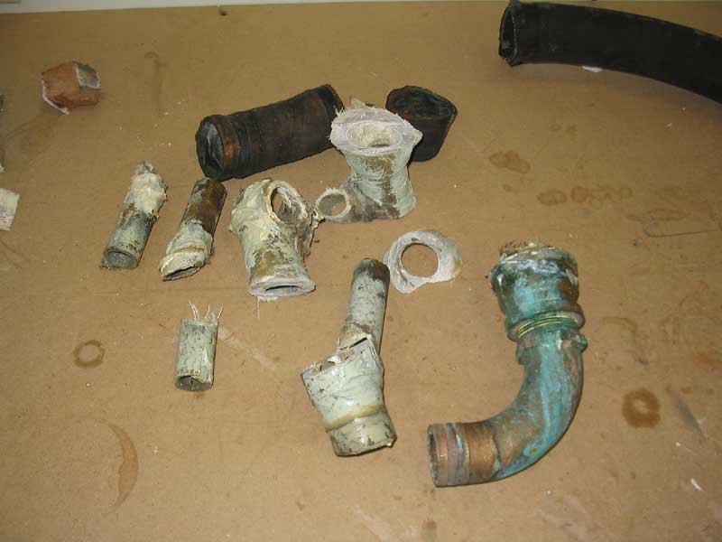
The resulting pile of pieces and parts |
|
 With
the fiberglass tubes cut away and the surrounding area prepped, my ultimate plan of attack formed. As it turned out,
the top of the new scuppers is exactly 2-1/2" in diameter, so it seemed that a sound plan would be to cut a 2-1/2"
diameter hole with a hole saw, into which the scupper would fit flush. Because of the tapered shape of the head of the
fitting, this size hole would also allow ample room for thickened epoxy adhesive, with which the scupper would be
permanently installed. With
the fiberglass tubes cut away and the surrounding area prepped, my ultimate plan of attack formed. As it turned out,
the top of the new scuppers is exactly 2-1/2" in diameter, so it seemed that a sound plan would be to cut a 2-1/2"
diameter hole with a hole saw, into which the scupper would fit flush. Because of the tapered shape of the head of the
fitting, this size hole would also allow ample room for thickened epoxy adhesive, with which the scupper would be
permanently installed.
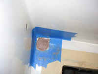
Before I could cut the large hole with a hole saw, however, I had to fill in the existing opening with
epoxy, so that the pilot bit on the hole saw would have something to bite into. So before I quit for the day, I
applied a couple layers of masking tape over the bottom of the two holes, and then mixed up a batch of thickened epoxy that
I troweled into the holes till they were roughly flush. I didn't worry about finesse, complete coverage, etc., since
the sole purpose of this epoxy was to provide something into which to drill. It would all end up being cut out again
when I cut out the large hole later. I left the epoxy to cure overnight before continuing. |
 |
|
Please click here to continue.>
|
|