|
Cockpit Structural
Repairs
This page was last updated on
January 30, 2002
Related Pages: Cockpit,
Page 2 Cockpit, Page
3
|
|
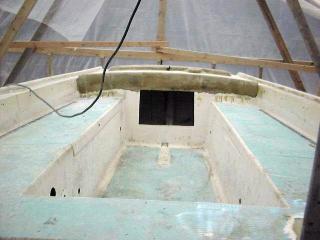 The cockpit,
like most other deck areas, needed a lot of work--basically, it looked like
hell. Besides the obviously bad condition of the cosmetics, the underlying structure
was weak--the deck crackled and flexed when walked upon. The root cause of this weakness
was that the cockpit is not cored, and the fiberglass is relatively thin--certainly thinner than it needs to be for proper support.
The factory installed some narrow longitudinal plywood stiffeners beneath the
cockpit sole, which were glassed in place. These did nothing to stiffen the
sole. The cockpit,
like most other deck areas, needed a lot of work--basically, it looked like
hell. Besides the obviously bad condition of the cosmetics, the underlying structure
was weak--the deck crackled and flexed when walked upon. The root cause of this weakness
was that the cockpit is not cored, and the fiberglass is relatively thin--certainly thinner than it needs to be for proper support.
The factory installed some narrow longitudinal plywood stiffeners beneath the
cockpit sole, which were glassed in place. These did nothing to stiffen the
sole.
The plan of attack was to grind off the gelcoat and laminate a layer
or more of 2mm Coremat over the seats, lockers and cockpit sole, following with one or two layers of additional cloth, especially in the well.
I hoped this would add the requisite stiffness to the weight-bearing surfaces,
but not interfere with the useful space beneath the cockpit, since I had plans
to install a new fuel tank there so that I could open up the starboard cockpit
locker. Therefore, the easy way out--adding braces and stiffeners--was not
going to work. Plus, this is hardly the best way to take care of the
problem anyway.
|
|
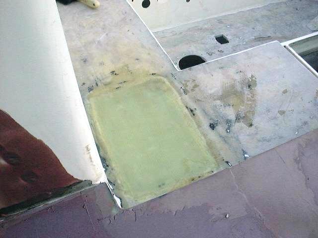
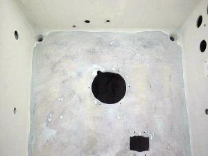
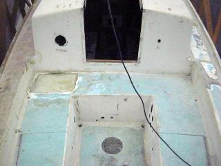 Also on the work list: patch the old gear lever access hole, patch the old gauge holes, and possibly add a larger deck plate or access hatch for better access to the stuffing box and rear of engine.
These photos were taken after the icebox loading hatch was removed and glassed
over (see the recore page for information on how I did
that). The new layers of Coremat and fiberglass will cover this area, and provide additional stiffness. Also on the work list: patch the old gear lever access hole, patch the old gauge holes, and possibly add a larger deck plate or access hatch for better access to the stuffing box and rear of engine.
These photos were taken after the icebox loading hatch was removed and glassed
over (see the recore page for information on how I did
that). The new layers of Coremat and fiberglass will cover this area, and provide additional stiffness.
The first step before beefing up the structure of the cockpit was to remove the cockpit locker covers. These were attached with piano hinges, which were fortunately--for the purposes of removal, that is--screwed to the cockpit with sheet metal screws. Had they been bolted, the removal would have been long and arduous. As it was, they came off quickly with my
screw gun.
|
|
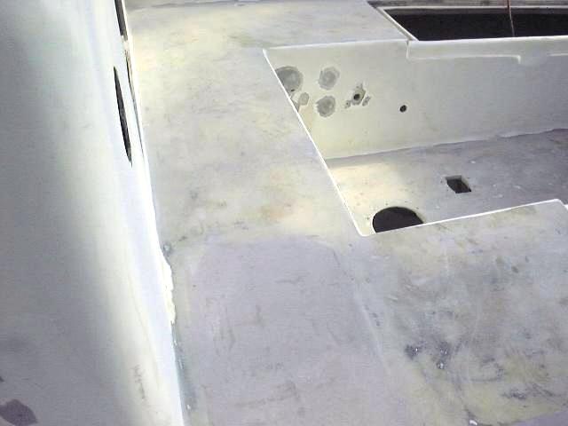
 I then removed any remaining hardware--the bronze deckplate over the stuffing box, the gasoline tank fill (on the coaming) and a small louvered vent where the blower used to be installed. These holes, along with the old holes from the icebox drain, engine
gauges, and floor-mounted gearshift lever, all required patching. I then removed any remaining hardware--the bronze deckplate over the stuffing box, the gasoline tank fill (on the coaming) and a small louvered vent where the blower used to be installed. These holes, along with the old holes from the icebox drain, engine
gauges, and floor-mounted gearshift lever, all required patching.
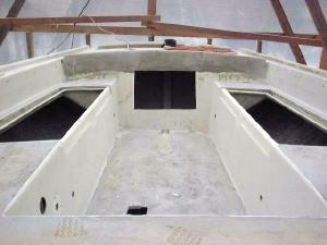
Next, I ground all the gelcoat off the flat cockpit surfaces that I intend to add material to--the seats and the sole. This was a
messy job, but my big 7" angle grinder (equipped with a soft backer pad)
made short work of it. I cleaned up some of the tighter spaces with my
smaller sander.
|
|
 I
planned to install a much larger deck access hatch in place of the small round
one that had been there. It was impossible to work with the little deck
plate that had been in place before. I wanted a good-sized opening so that
I could easily access the stuffing box, cockpit scupper valves, and the rear of
the engine. If you'd like to jump ahead, click here
to see how I eventually installed the cockpit sole access
hatch. I
planned to install a much larger deck access hatch in place of the small round
one that had been there. It was impossible to work with the little deck
plate that had been in place before. I wanted a good-sized opening so that
I could easily access the stuffing box, cockpit scupper valves, and the rear of
the engine. If you'd like to jump ahead, click here
to see how I eventually installed the cockpit sole access
hatch.
After some thought, I decided that I should add
some balsa core over the top of the cockpit sole (instead of Coremat), and then fiberglass
over the top. This would add substantially more stiffness.
To
begin, I sanded all the vertical surfaces with 80 grit, same as the cabin trunk. This was a preliminary sanding only--more to come. I also sanded the inside of the cockpit coamings and the starboard deck aft of the recore repairs.
|
|
|
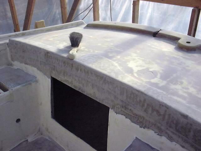
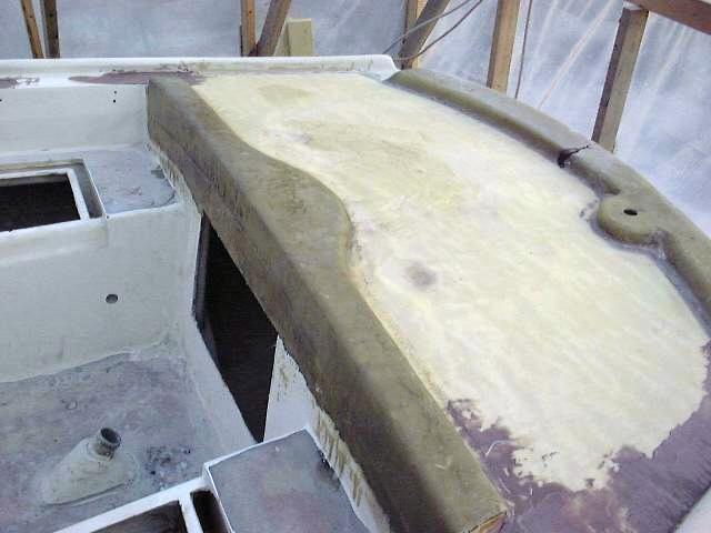 The
poop deck and ice hatch needed a little more attention before moving on to the
fairing and strengthening of the cockpit. I wanted to add a little extra
fiberglass to both areas--to the raised forward portion of the poop deck, where
I intend to install a mainsail traveler, and to the center of the filled-in ice
hatch (see the recore page for how I did that
originally), which was still lower than the surrounding area, and I didn't want
to fill it with just fairing compound before laminating over the top. The
poop deck and ice hatch needed a little more attention before moving on to the
fairing and strengthening of the cockpit. I wanted to add a little extra
fiberglass to both areas--to the raised forward portion of the poop deck, where
I intend to install a mainsail traveler, and to the center of the filled-in ice
hatch (see the recore page for how I did that
originally), which was still lower than the surrounding area, and I didn't want
to fill it with just fairing compound before laminating over the top.
 Ice
Hatch--click for full size Ice
Hatch--click for full size
This was a simple task that only took a few minutes, and I
won't bore you with the details. The procedure is the same, in general, as
that used when I laminated the port foredeck earlier in the project. I
only added one additional layer of cloth to the rail. When the resin
kicks, I will return to begin fairing the poop deck and traveler rail. I
will also begin repairing the taffrail very soon, as that needs strengthening
and spot repair.
|
|
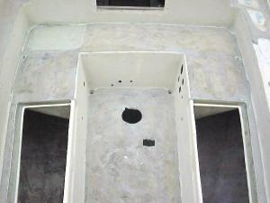
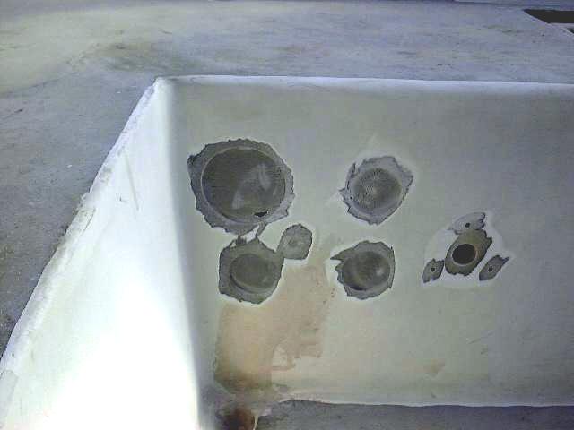 Next,
I laminated some fiberglass cloth on the back side of the cockpit sides, over
the old gauge holes and the old icebox drain, among others. This will
provide me a backing so I can fill these and fair them flush with the
surrounding fiberglass; I will not be reusing the old gauge holes, as I will be
installing a newly made-up instrument panel elsewhere in the cockpit
later. I also stuffed epoxy-saturated cloth into the holes on the side of
the cabin trunk where the old running lights were installed--there's a hollow
space there--so that, when kicked, I could fill these as well. The running
lights will be relocated to the bow pulpit. Next,
I laminated some fiberglass cloth on the back side of the cockpit sides, over
the old gauge holes and the old icebox drain, among others. This will
provide me a backing so I can fill these and fair them flush with the
surrounding fiberglass; I will not be reusing the old gauge holes, as I will be
installing a newly made-up instrument panel elsewhere in the cockpit
later. I also stuffed epoxy-saturated cloth into the holes on the side of
the cabin trunk where the old running lights were installed--there's a hollow
space there--so that, when kicked, I could fill these as well. The running
lights will be relocated to the bow pulpit.
Next, I ground around the edges, creating a feather that
makes for a softer edge for filling. This will allow more successful
fairing. Next time I mixed up a batch of fairing compound, I gooped some
into those areas. Please click here
for more details on this job.
|
|
  I also applied a coat of putty to the poop deck
and sanded it smooth a couple days later. Another
application will be necessary on the flat surface, as well as on the raised
portion at the forward end where the traveler will be located. The ice hatch
is also finally faired flush with the surrounding seat, so I can think about
laying up the Coremat and new cloth next time the weather is warm
enough. I also applied a coat of putty to the poop deck
and sanded it smooth a couple days later. Another
application will be necessary on the flat surface, as well as on the raised
portion at the forward end where the traveler will be located. The ice hatch
is also finally faired flush with the surrounding seat, so I can think about
laying up the Coremat and new cloth next time the weather is warm
enough.
|
|
|
Please
click here to continue the cockpit project!
|
|