|
The Ever-Settling
Waterline (Page 3)
This page was last updated on 9 October 2002.
Striking
the New Waterline, 1" Above the Actual Load Waterline
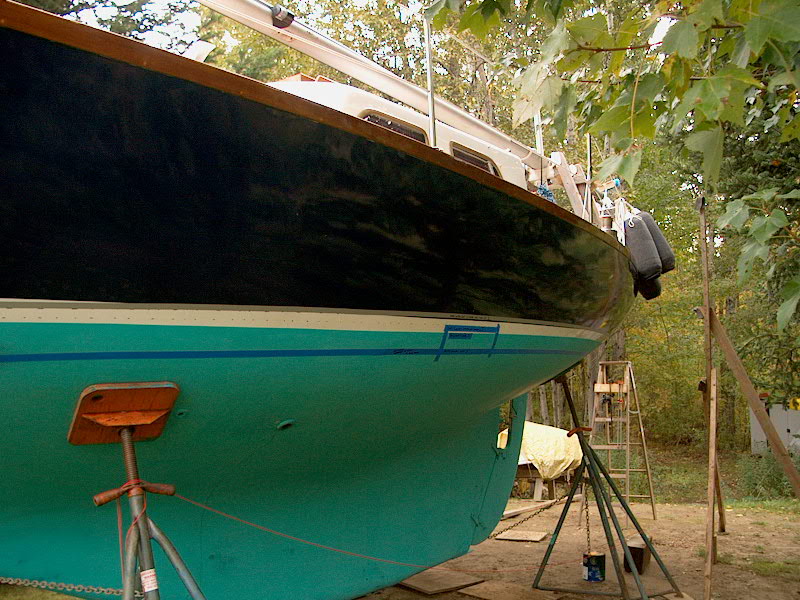
Later, I continued work on the
new waterline. After setting the strings up on both sides at the new
height (1" above the existing waterline), I eyed things from several angles
to ensure that it looked basically right before I continued, satisfied as much
as I could be given the visual limitations of the string system.
|
 |
I followed the same
procedure as I used to mark my test waterline earlier
(see
page 2).
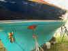
I began amidships, bringing the string in at a predetermined and equal
point on each side of the boat, and taped the string where it touched
the hull. Because the black marker wouldn't show up on the dark
blue hull in this area, I marked the string height with a short piece of
tape, applying the tape just below the string. Later, as the
string entered the white old boottop, I returned to using the
marker. |
 |
 |
I marked the forward half
of the boat first, following the same procedure as before--pull the
string in towards center till it touched the boat 4" - 6" away
from the last mark, then tape it place, mark the line, and repeat until
the string touched the stem. |
| Sorry, no picture of
this! Oops! |
To make it a little
easier to mark the complicated curves of the boat beneath the counter, I
found that it helped to remove the tape holding the string into the bow
sections, leaving it taped only amidships at maximum beam, and bringing
the forward end of the string further outboard on the horizontal support
to ease the tension on the string as I pulled it in beneath the counter. |
 |
 |
When I had one side
completely marked with the string, I removed it and applied masking tape
to the hull, following the top edge of the pen and tape marks. I
faired the line by eye as I applied the tape, and didn't try to hit
every mark exactly, concentrating instead on every other mark or
so. When I was satisfied that the line was right on the first
side, I repeated the entire process above on the other side of the
boat. The silver tape I used is 3M #225, a 30-day release tape
that I really like for virtually everything. It never leaves
adhesive behind, stretches nicely, is strong, and allows for a fine
paint line too. It's pricey as anything, but well worth it. |
 |
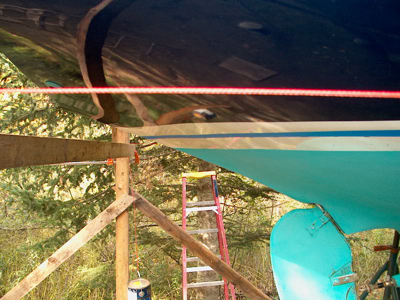
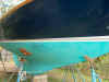
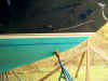
The counter is by far the
most challenging to mark and tape. The string, when pulled in and
taped as described above, was fairly accurate, but this tape line still
required much fairing by eye, checking it from several different
angles and eye-heights, particularly with the eye on the same plane as
the line. I used blue tape for this because it's cheaper to pull
off and start over, and I only had a limited amount of the silver tape
on hand. The height of the camera is a bit off in this photo, but
it attempts to capture the apparent straightness of the tape line under
the counter. Of course, looking at it from beneath shows all the
various curves required to get this optical straightness. |
 |
 |
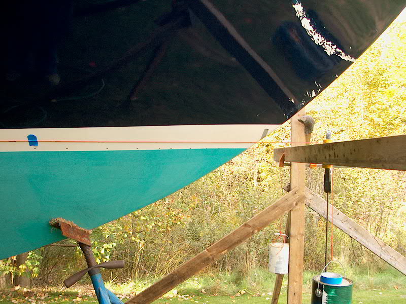
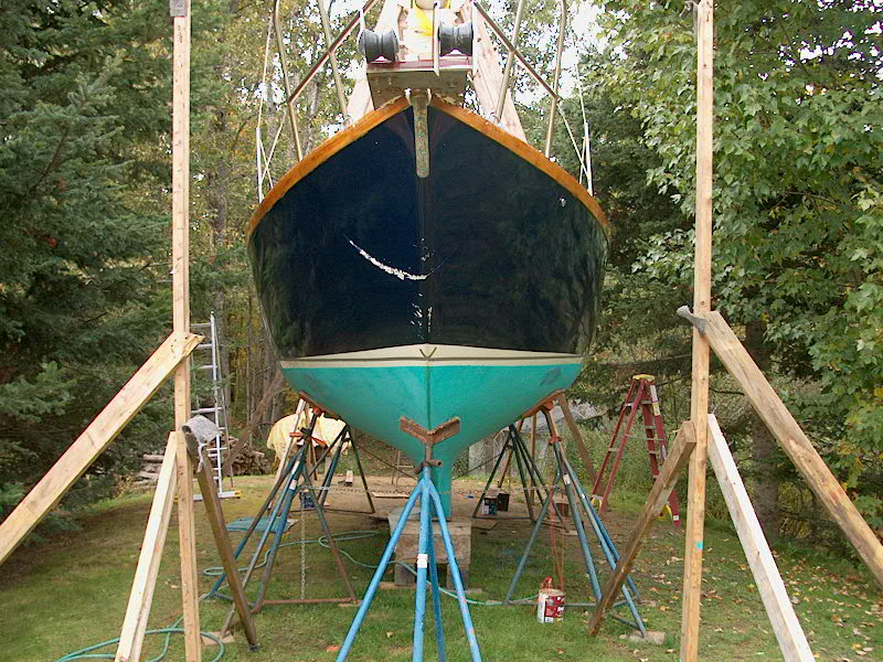
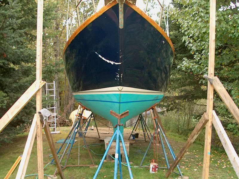
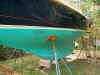
Here are the new tape
lines (in which the new height of the antifouling paint will be brought
to the bottom of the tape) seen from the bow and stern. The port
side beneath the counter is still a little off to my eye, but I'll
correct that on another day. In visualizing the new line, it's
important to ignore the old boottop and bottom lines, which are
irrelevant to the new line. Still, their presence tends to lead
the eye astray and fool it into thinking the new line is funky. |
 |
 |
Because of the difficulty
in properly visualizing whether the new line is "right" or
not, I needed some additional confirmation. After eyeing the thing
from left, right, backwards and forwards, I decided to compare it to the
original, as-designed waterline mark--the lower scribe mark, now
mostly covered with bottom paint. There was enough of it visible,
however, for me to run tape lines along it on both sides. |
 |
 |
|
In doing this, and
wasting 65' of tape, I wanted to confirm two things: that the
original designed waterline was indeed planar, like my new one will be;
and that my new line appeared to be parallel to this original one,
5" beneath. I was happy to see that my new line did indeed
parallel the original designed waterline (DWL). |
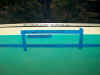 |
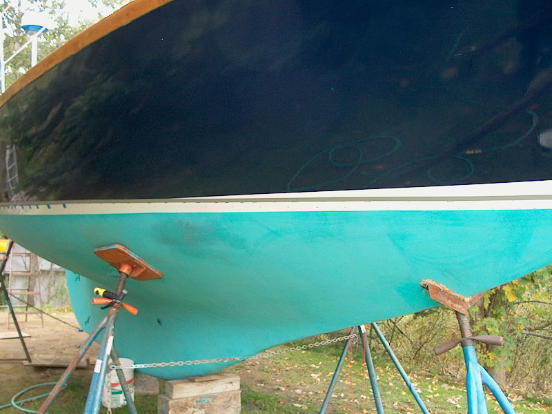
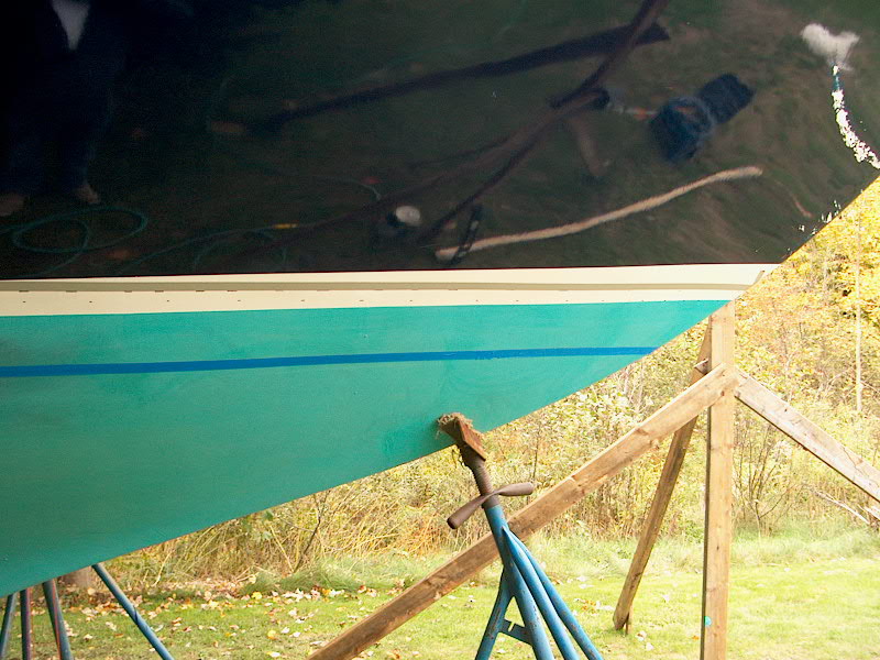
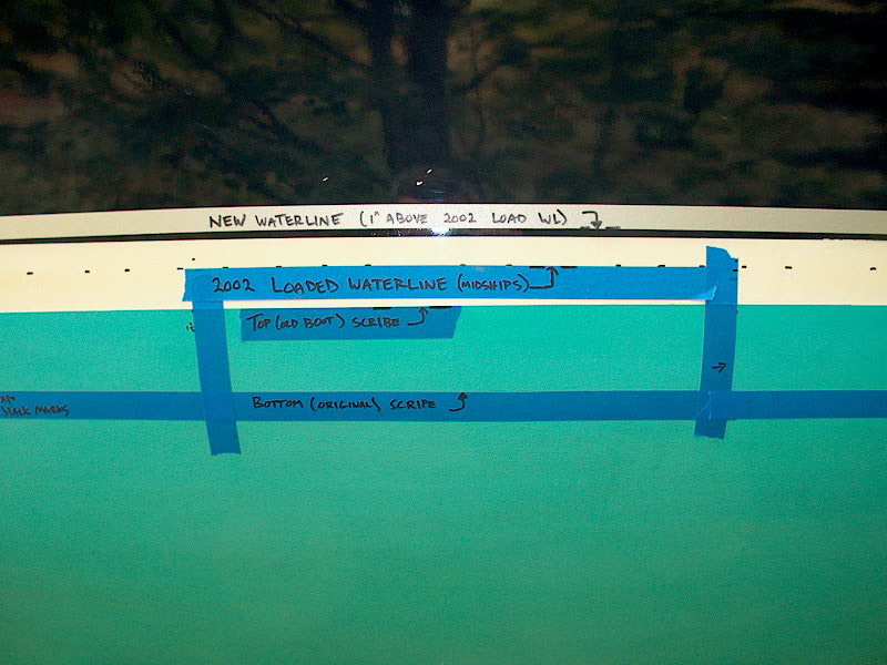
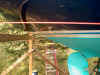
I call this photo
the "Plimsoll Mark" because the multiple tape marks and
heights resemble the loading marks that all cargo ships have on their
sides to show their proper loaded depth. This photo shows the
drastic changes that are happening here. The new, planar waterline
being struck is about 5" above the ridiculously low original DWL, designated
by the lowermost tape mark. The labels drawn on the tape should be
self-explanatory. |
 |
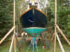
This photo shows
the old and new tape marks on the port side, and also provides a
placement reference for the detail photo shown directly above. |
|
|
From here, I've reached the point
of no return: the next step is to begin sanding off the Awlgrip beneath my
new tape line in preparation for the new bottom paint. The Awlgrip should
be completely removed because it is not designed to be submerged, and will
ultimately fail beneath the antifouling paint, which of course will lead to
antifouling paint failure as a result. Needless to say, I shall check and
double check my lines, and be sure everything is absolutely right before I take
this next irreversible step.
To recap, again, in case my
descriptions are at all confusing:
-
The BOTTOM
SCRIBE mark (what one might term the original Designed WaterLine, or
DWL) is straight and planar.
-
The UPPER
SCRIBE mark (the upper edge of the original boottop, and the
point to which I raised the antifouling paint when I repainted the hull) is
NOT straight and planar; rather, it incorporates a curve, or sheer, which is
proper for an upper boottop edge, but not for the waterline. This
upper scribe mark is also the bottom edge of my current boottop; the fact
that it is not planar leads in large part to the strange waterline we had
when the boat was fully loaded this season.
-
The TOP OF
MY CURRENT BOOTTOP is also curved, or sheered.
-
Finally, what
I am trying to accomplish is to have the new waterline (edge of the bottom
paint) parallel to the water, and straight and planar--and more reflective
of where the boat actually floats. This will give the new boottop a
straight lower edge also, and I will curve, or sheer, the top edge for an
attractive look.
Please click here to
continue.
|
|