|
Mast Upgrades and
Maintenance
This page was last updated on 4
April 2003.
New Masthead (Anchor) Light
New
Spreader Bases | Standing
Rigging Maintenance and Inspection | New
Jumper Stays | Boom
Support Cable
|
|
 Spreader Bases Spreader Bases
I
decided to replace my original cast aluminum spreader bases after a damaging
incident during our 2002 cruise. During a raft-up with a friend's
Triton, an inconsiderate powerboat sped by at "maximum wake speed",
causing the masts on our two boats to collide several times before the wake
settled down. The impact sheared one of the spreader bases on our
friends' boat, calling into question the structural integrity of our own
spreader bases--even though they looked OK. To play it safe, I decided
that 40 years was ample service for these parts, so I ordered a new set from my
local rigger. He found a place where these castings are still a
stock item; I cannot remember the name.
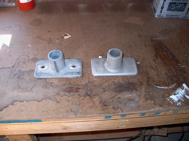
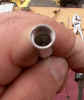
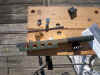
 The new bases are nearly
identical to the old, although the wall thickness of the spreader socket is
thicker than on the original (always a good thing). The castings came with no holes drilled, so
I'll have to take care of that. The new bases are nearly
identical to the old, although the wall thickness of the spreader socket is
thicker than on the original (always a good thing). The castings came with no holes drilled, so
I'll have to take care of that.
|
 Removing the old bases
from the mast was easy, a matter of unbolting
two stainless steel bolts, which were fortunately in excellent condition.
Despite a weathered appearance on the visible parts of the old bases, they
looked generally sound at first. Once I removed them, however, it
became clear that they had been operating on borrowed time. The back
sides of the bases, where they had rested against the mast all those
years, were quite badly corroded and chalky in appearance, as one might
expect after 40 years of outdoor marine service. Nothing
particularly alarming, but deteriorated enough that I was unquestionably
happy that I had taken the time to remove them. Removing the old bases
from the mast was easy, a matter of unbolting
two stainless steel bolts, which were fortunately in excellent condition.
Despite a weathered appearance on the visible parts of the old bases, they
looked generally sound at first. Once I removed them, however, it
became clear that they had been operating on borrowed time. The back
sides of the bases, where they had rested against the mast all those
years, were quite badly corroded and chalky in appearance, as one might
expect after 40 years of outdoor marine service. Nothing
particularly alarming, but deteriorated enough that I was unquestionably
happy that I had taken the time to remove them.
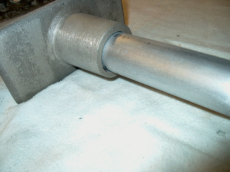
Once the boat was back home in the
backyard, I brought the rigging into the shop for storage, and at that
time tried the fit of the new spreader bases with the existing spreader
tubes. The tubes didn't fit into the new sockets, though it was
close. I determined that the problem was with the roughness of the
casting, rather than a complete misfit, so I stored the stuff out of the
way for the moment with plans to bring it all out during the winter and
make the necessary adjustments.
|
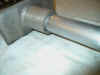 When
I finally did begin work on the new bases in earnest, I found that it took
very little work with a file, first, and a small drum sander attachment in
my drill to remove the casting burrs and ream the sockets out enough for a
good fit. Once this had been done, each spreader fit home with a
satisfying clunk as it hit the bottom of the socket. I spent some
extra time cleaning up the spreader tubes, removing the rubber spreader
boots (which had been in place for two seasons), and cleaning up the
spreader tip castings. I even unscrewed the flag halyard eyes from
each spreader and reinstalled them with a good coating of waterproof
grease at each screw location, to help isolate the stainless steel screws
from the aluminum. When
I finally did begin work on the new bases in earnest, I found that it took
very little work with a file, first, and a small drum sander attachment in
my drill to remove the casting burrs and ream the sockets out enough for a
good fit. Once this had been done, each spreader fit home with a
satisfying clunk as it hit the bottom of the socket. I spent some
extra time cleaning up the spreader tubes, removing the rubber spreader
boots (which had been in place for two seasons), and cleaning up the
spreader tip castings. I even unscrewed the flag halyard eyes from
each spreader and reinstalled them with a good coating of waterproof
grease at each screw location, to help isolate the stainless steel screws
from the aluminum. |
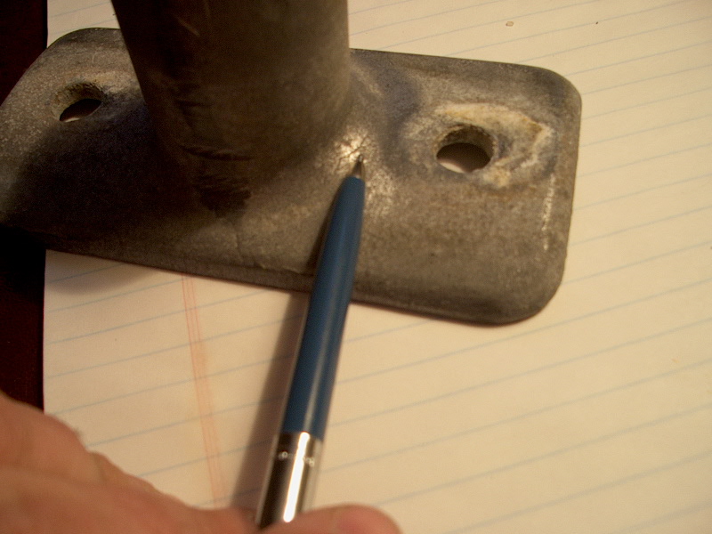
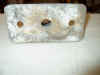
 With
the fitting work complete, I took a moment to scrape off the crusty
corrosion from the old bases and clean them up for inspection and storage
as spare parts. While doing this, I noticed a couple alarming things
about the bases that made me extra happy about installing new
replacements. First, on both parts, there were some casting
inconsistencies on the back sides, air pockets in the metal that just
didn't look encouraging. And, more seriously, on the starboard
spreader base, I noticed--upon close inspection--a hairline crack along
the top edge of the juncture between socket and base. The crack
extends over most of the top half of the socket, and is quite hard to see. With
the fitting work complete, I took a moment to scrape off the crusty
corrosion from the old bases and clean them up for inspection and storage
as spare parts. While doing this, I noticed a couple alarming things
about the bases that made me extra happy about installing new
replacements. First, on both parts, there were some casting
inconsistencies on the back sides, air pockets in the metal that just
didn't look encouraging. And, more seriously, on the starboard
spreader base, I noticed--upon close inspection--a hairline crack along
the top edge of the juncture between socket and base. The crack
extends over most of the top half of the socket, and is quite hard to see.
This is
exactly the sort of crack that leads to catastrophic failure someday if
it's not noticed, and it scared me to realize that, had it not been for
our mast-banging incident during our summer cruise that led to the failure
of our friends' spreader base, we might not have been inclined to replace
the bases, at least not unless a close routine inspection had located this
crack.
I am now aware of several Tritons that have
recently suffered spreader base failures, probably caused by similar
casting flaws like this. I guess that these relatively poor (to
begin with) castings have just about seen all the stress they can handle
after 40 or more years, and simply fail under not-abnormal strains.
Beware! |
| Later, I
carefully drilled the boltholes for securing the bases to the mast,
using the old spreader bases as a guide, and also drilled for the cotter
pin that holds the spreader tube inside the base. Creating these
holes was a matter of careful measuring, remeasuring, and measuring
again; the aluminum cut easily.
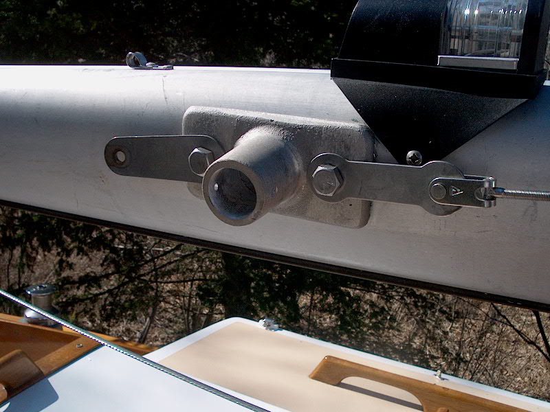
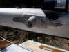 Several
weeks later, I installed the new spreader bases on the mast, bolting
them in place with the original bolts (which seemed to be in good
condition still). I applied a thin coat of waterproof grease to
the underside of the bases to help isolate them from the mast. Several
weeks later, I installed the new spreader bases on the mast, bolting
them in place with the original bolts (which seemed to be in good
condition still). I applied a thin coat of waterproof grease to
the underside of the bases to help isolate them from the mast.
|
|
Standing
Rigging Maintenance
In the fall, I removed all the
standing rigging from the mast after it was unstepped. I carefully coiled
each wire and stored them in the shop for later inspection and
maintenance. During the winter, I pulled out the wires and began some
basic maintenance. Mostly, I worked on a general wire inspection,
concentrating on the condition of the swages but also carefully inspecting the
wires for signs of damage or broken strands. I also lubricated the
turnbuckle threads with some of my new favorite waterproof grease, which I now
use all over the place. By unscrewing both ends of the turnbuckle all the
way, and then spreading a small bead of the grease on the threads and then
screwing them in all the way, I achieved a consistent, thin coating of the
grease on all the threads. Not only will this make the turnbuckles easy to
adjust and prevent them from freezing, but it will also protect the threads from
corrosion and salt spray.
|
 I
use a blue waterproof multi-purpose waterproof grease on the turnbuckle
thread, as well as on many other onboard projects. The stuff I use
is leftover from years ago, when I got it from an old OMC (outboards)
dealer. I have a huge 8 oz. tube of the grease, and since a
little goes a long way, I may never need more. It's excellent
stuff, though, and I'm posting the information here so that anyone
interested can try and find a substitute that's currently available. I
use a blue waterproof multi-purpose waterproof grease on the turnbuckle
thread, as well as on many other onboard projects. The stuff I use
is leftover from years ago, when I got it from an old OMC (outboards)
dealer. I have a huge 8 oz. tube of the grease, and since a
little goes a long way, I may never need more. It's excellent
stuff, though, and I'm posting the information here so that anyone
interested can try and find a substitute that's currently available. |
|
Replacing
the Jumper Stays and Struts
I discovered that at least one of
my jumper stays had indeed been damaged when the jumpers were ruined last
August--there was a 2-3" section where the wire was abraded. I
decided to replace both wires as a precaution. Whether or not it is
financially the most efficient, I ordered Sta-Lok terminals and wire in order to
make the new stays up myself. The swaged ends are likely less expensive,
even when the rigger's labor charges are included, but I want to start shifting
to Sta-Loks in the future, and want some more practice with the terminals.
Materials ordered to replace the
jumper stays:
-
41' of 1/8" stainless
steel wire, 1x19
-
2 Sta-Lok fork terminals for
the top end, 1/8" size
-
2 Sta-Lok turnbuckle studs
for the lower ends, 1/8" size with 1/4" threads
I had
installed a Norseman terminal two years ago when I built the headstay and roller
furler, but that was my only experience with these terminals. They
really are quite easy to install, once you've done one or two. The basic
process is documented below, at least partially. The two fork terminals
arrived first (the studs were on backorder), so I installed the four ends on
different days. The photo documentary below may span both days, since some
of the pictures from the first day were out of focus or otherwise
unusable. So, in some of the photos you'll see fork terminals, and in
others you'll see stud terminals (designed to thread into turnbuckle
bodies). One
thing I noticed is that the installation procedure is slightly different between
Norseman and Sta-Lok terminals. But the basic process is the same.
Related
Link:
Sta-Lok
Installation Instructions from the Web |
|
Typical Installation
Procedure--Stalok Terminals |
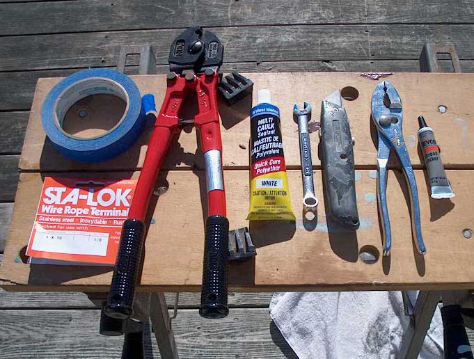
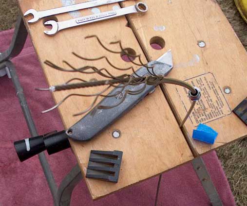
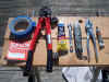
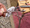
First, I gathered
all the tools needed for the job:
- Cable cutters to cut the wire cleanly
- Tape, to wrap around the wire 12"
below the end
- The manufacturer's instructions
- Knife to help start the untwisting of
the wire
- Wrench for tightening the terminal
- Loc-Tite (blue) for the threads
- Polysulfide sealant
|
 |
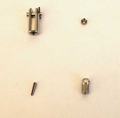
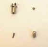
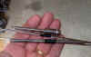
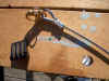
A typical Sta-Lok
fork terminal includes these parts (clockwise from left):
- The main terminal end (body)
- The wire former (goes inside the
female threads of the body)
- The socket end
- The wedge
|
 |
|
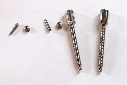
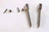
A typical Sta-Lok stud
terminal includes these parts:
|
 |
|
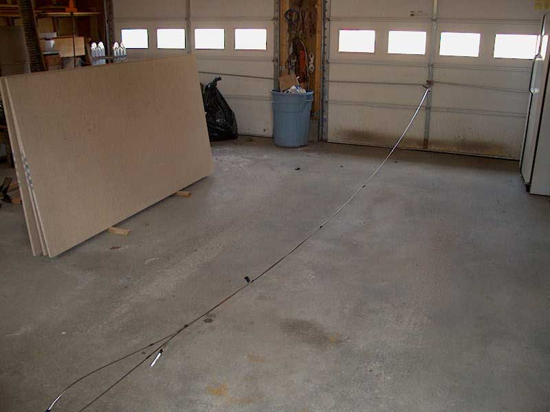
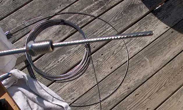
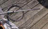
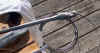
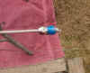
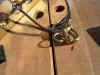
In order to ensure that
the new stays ended up the same length as the old ones, I decided to
stretch the old (existing) wire out in my garage. After I had
installed the fork terminals on the two ends of the new wire, I was
ready to cut it to length so I could install the stud terminals at the
lower ends. Since the Sta-Lok terminals are of different lengths
from the original swaged terminal ends, measuring the wire alone would
not be sufficient to preserve the overall length. So, I tied the
three forked ends (two on the new wires, one on the old) together and
secured them to my garage door, and stretched the three cables out
together. |
 |
|
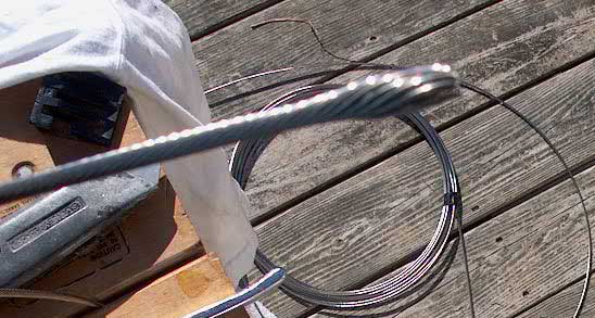
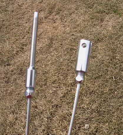
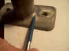
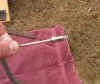
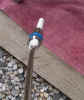
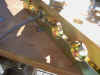
With the new and old
cables together, and comparing the length of the new studs versus the
old, it was easy to visualize exactly where the new cables should be cut
to length. I erred just slightly on the side of cutting the new
ones a bit shorter, since I knew that I had had the turnbuckles
tightened about halfway in the old setup--so slightly shorter (1/8"
or so only) wires would still be plenty long, but I wouldn't have to
risk bottoming the studs out if I decided to tighten the stays more than
I had previously. You can see the length difference between the
old and new terminals in this photo. |
 |
|
The first step is to cut
a clean end on the wire, if one doesn't already exist. Good cable
cutters are crucial for this, though you could theoretically use a
hacksaw. The instructions call for installing some tape about 12'
down from the end, just to hold the strands in place if needed.
When the clean end is cut, slide the socked end down over the wire,
ensuring that the threads face the cut end of the wire. |
 |
|
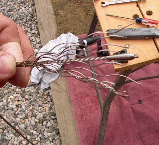
Next, begin to unlay the
outer wire strands from the inner core. A knife is helpful here to
get things started, but they unlay easily once you've gotten it
going. Untwist the outer strands down about 2-3" from the
end, exposing the central core. |
 |
|
Slide the wedge over the
core, with the wider end facing the cut end. Leave about 1/8"
of the core showing above the wedge (at least for the 1/8" wire and
fittings I used for this job--check the instructions to see if this
varies). |
 |
|
When the wedge is
positioned, relay the outer strands around the core and over the wedge,
ensuring that they lay in properly and evenly around the wedge.
There's a slot in the wedge, which allows it to compress over the core
later in the installation process, and you need to ensure that none of
the wire strands fall into this slot now. The wires wrapped around
the wedge makes it look like a snake that swallowed a hamster or
something. |
|
|
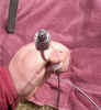
Slide the socket up as
far as it will go beneath the wedge, and install the former inside the
female part of the body terminal. Then, screw the end onto the
socket, using a wrench but only tightening with as much force as can be
applied with the wrench and holding the end with one hand. Then,
unscrew the end again; this allows inspection of the wire end, to make
sure that the wire strands have been properly compressed and formed
around the top of the wedge. |
 |
|
This shows the wire former inside the female
part of the terminal. |
 |
|
Assuming it looks right,
continue with the final assembly. Squirt some Loc-Tite thread
locker onto the male threads of the socket, and squeeze a bead of
sealant into the female end. The sealant may be polysulfide
or silicone, but if silicone is used, ensure that it is not the type
that contains acetates that can adversely affect stainless steel over
time. If the silicone is of the hardware store variety, and/or
smells vaguely like vinegar, do not use it here. It's a safer bet
to use polysulfide. |

|
|
With the sealant applied
and thread locker on the threads, screw the terminal together
again. Sealant should squeeze out the base of the socket onto the
wire when properly installed. Tighten the fitting as described
above, and wipe off any excess sealant. |
 |
|
The fitting is now
installed, and retains 100% of the strength of the wire alone. It
can be unscrewed in the future for inspection, and all parts of the
terminal except the wedge can be reused on a new wire in the future.
|
 |
|
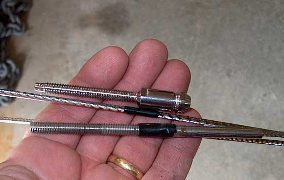
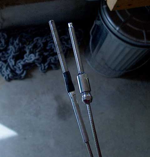
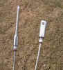
The old (left) and new
studs on one of the wires. You can see that the new wire assembly
is just a tiny bit shorter than the old, as described above. |
 |
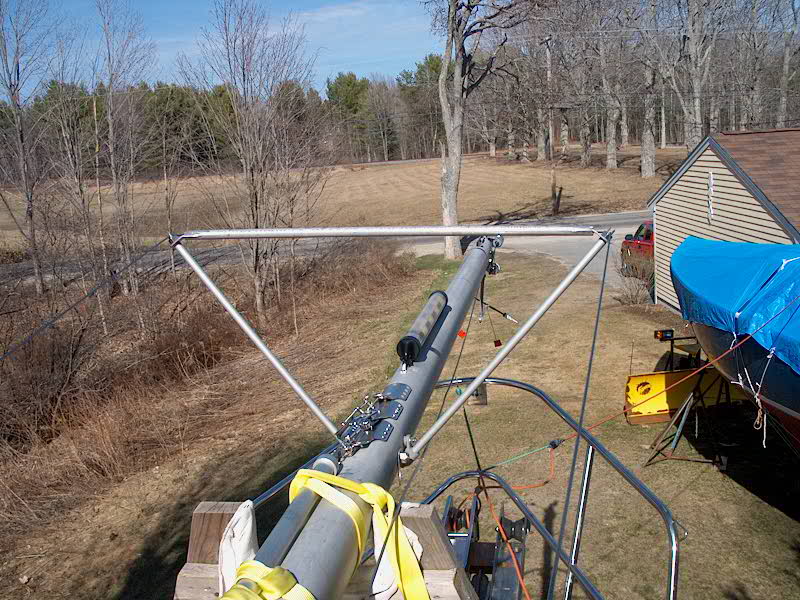
Several
weeks later, I decided it was time to check the fit of my new jumper
struts and the new stays, just in case there was a problem. First,
though, I had to reinstall the main spreader bases (see above), so that
the lower jumper stay tangs would be in place. Next, I discovered
that the upper tangs (at the masthead) required a new hole for the upper
end of the stays, since the Sta-Lok fork terminals were not as deep as
the original swaged terminal ends. There was plenty of metal
there, so it was easy enough to drill the new holes a little further
down. With the new holes, and the upper tangs reinstalled at the
masthead, I secured the two new stays.
 Next,
I fit the new jumpers. The rigger had left the tubes a bit
overlong to ensure that they fit perfectly, so I had to figure out how
much to cut off. Holding the various pieces in place, I determined
that about 2" needed to come off each strut, so I made the
cuts. Success! The new struts now fit perfectly. I
placed the stays in the slots at the end of each adjusting thread and
tightened the turnbuckles enough to draw things up. Everything
worked well; there was still plenty of room to tighten the turnbuckles
more, which I will do before launch day. But for now, the main
purpose had been satisfied: my new stays, and the new jumpers, all
fit and worked as they were supposed to. Next,
I fit the new jumpers. The rigger had left the tubes a bit
overlong to ensure that they fit perfectly, so I had to figure out how
much to cut off. Holding the various pieces in place, I determined
that about 2" needed to come off each strut, so I made the
cuts. Success! The new struts now fit perfectly. I
placed the stays in the slots at the end of each adjusting thread and
tightened the turnbuckles enough to draw things up. Everything
worked well; there was still plenty of room to tighten the turnbuckles
more, which I will do before launch day. But for now, the main
purpose had been satisfied: my new stays, and the new jumpers, all
fit and worked as they were supposed to.
|
|
Boom
Support Cable
I thought it would be nice to
install a boom support cable running from the backstay to the end of the boom
when at rest. I like these because they allow the boom to be
tightly and easily positioned at a proper height, both for aesthetics and to
better clear the cockpit. Having the boom tightly positioned reduced wear
and tear on its various fittings.
To
create the cable, I used a hand swager and readily-available crimping
parts. For the wire, I chose a length of 7x7 stainless steel cable.
I can't install the backstay end till the boat is in the water and rigged, but
decided to go ahead and swage a loop and shackle onto the lower end now.
Because this is a low-stress, non-critical component, hand swaging is
acceptable; it should never be used for most rigging purposes, however, as it
lacks the strength needed.
|
Typical Installation
Procedure--Hand Swaging |
|
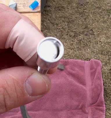
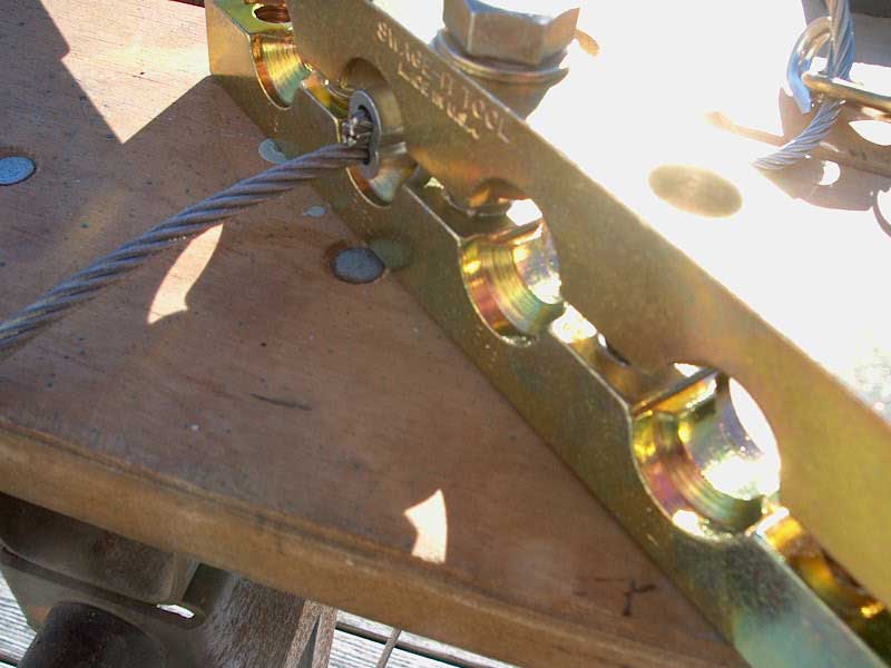
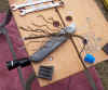
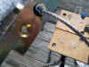
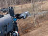
First,
I collected the tools and parts needed. For my particular loop and
shackle, I needed a wire thimble of the proper size (5/32" cable),
a length of 5/32", 7x7 stainless steel cable, one 5/32" crimp
fitting, and the hand swaging tool.
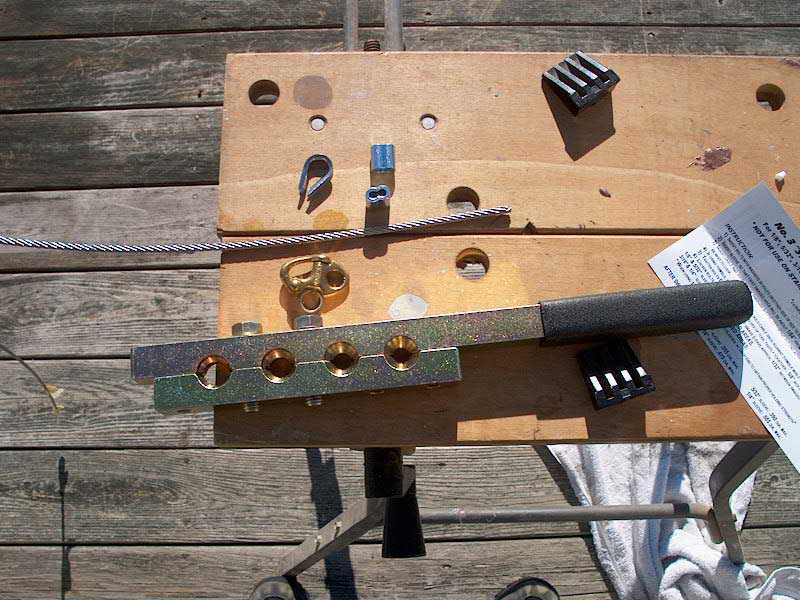
The hand swager couldn't be
simpler: you install the two bolts on either side of the proper
hole in the tool (it accepts four different size fittings), install the
crimp fitting inside, properly positioned so that the swage will be
close to one end (you do 2 or more crimps for each terminal), and simply
tighten the bolts evenly to pull the two halves of the tool together,
pressing the fitting tightly onto the wire. |
 |
|
With
the fitting positioned in the tool and light pressure on the bolts to
hold it, I ran the cable through one side of the fitting. I
slipped a thimble over the end of the shackle I was using, and ran the
wire through the eye and over the thimble, then back through the other
side of the swage fitting inside the tool. |
 |
|
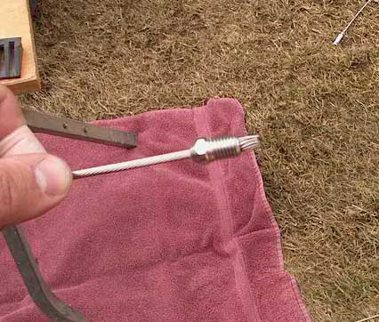
Leaving
a small amount of the cable protruding through the fitting, I tightened
the slack out of the other side of the cable, carefully positioning the
thimble and wire as I did so. Once the slack was out, and things
properly positioned, I held things in place and started cranking down
the bolts on the tool. |
 |
|
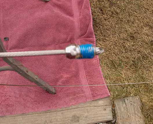
Ensuring
that the cables didn't pull our or fall off the thimble, I tightened the
two bolts evenly until the swage was complete. Then, I backed off
the bolts, repositioned the fitting inside the tool, and repeated the
process, creating a second swaged area on the fitting. Depending
on the length of the fitting, you should have 2, 3, or 4 crimps on each
fitting. The small size of this one prohibited more than two
crimps. |
 |
|
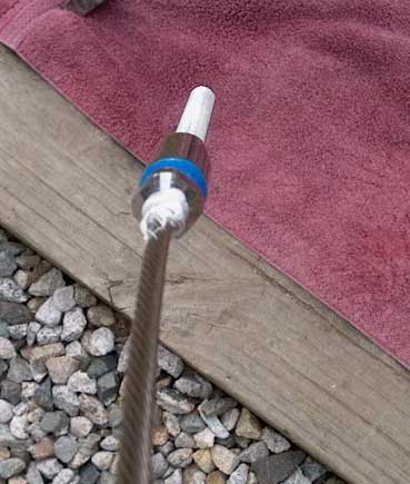
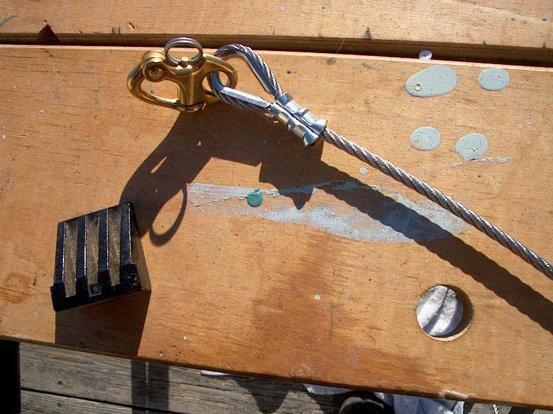
This
is the finished product. |
 |
Once the boat is rigged, I'll
complete the installation of the boom support cable by clamping the other end of
this cable to the backstay at the appropriate height. More to come.
|
|
Davis
Megalight (Anchor Light)
Being stupidly and
unnecessarily power-miserly, I never enjoyed leaving the old anchor light on
all night long. It just caused me stress and poor sleep. Dumb, I
know--but sometimes one just has a mental block that one can't get by.
I hoped for a better solution.
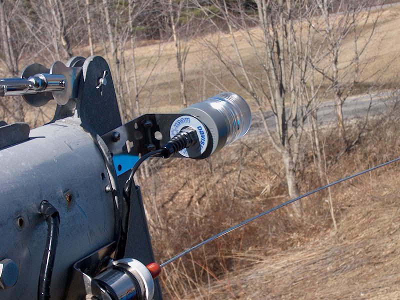
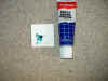
I found it in the Davis
Megalight, a photosensitive, energy efficient light designed for this
use. OK, OK, supposedly they are not as bright as "real"
masthead lights--who really knows, actually--but it's good enough.
Besides, it's better than not showing the light at all, which was my choice
much of the time.
Installing the new light was
a snap. It comes with its own bracket and wire lead, so all I had to
do was remove the existing lamp from the masthead, snip off the wires, and
install the new light in its own bracket, a much slicker arrangement than my
original setup anyway.
Click
here to see how I originally installed the old masthead light.
 With
the new light bracket installed, I simply connected the wiring harness
to the existing wires in the mast, using heat-shrink connectors. Then,
as before, I wrapped the wire in black electrical tape to keep it neat and
less ugly, and secured the wire around the VHF antenna, as before. With
the new light bracket installed, I simply connected the wiring harness
to the existing wires in the mast, using heat-shrink connectors. Then,
as before, I wrapped the wire in black electrical tape to keep it neat and
less ugly, and secured the wire around the VHF antenna, as before.
|
|