|
The Rudder and
Shafting
This page was last updated on 19
August 2001
The
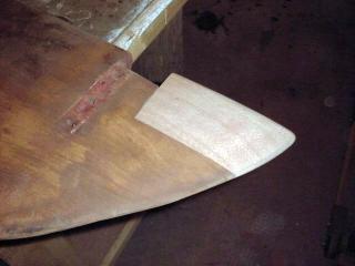
original mahogany rudder was in surprisingly good shape, except for a small chunk that was broken away from the
very bottom edge. Although repair of this was not essential, I nonetheless decided to remove the rudder and recondition it.
|
 |
 |
|
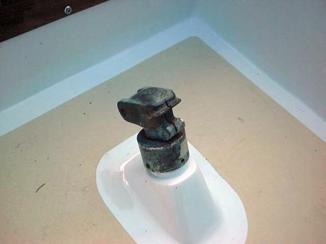
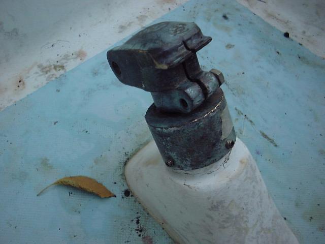 Removal was fairly straightforward. First, I removed the
tiller head, a relatively simple task as it was only temporarily installed anyway, and the upper "bearing", so to speak--less a bearing in actuality than a simple bronze casting with a hole through it. Once these pieces were removed, there were
no further obstacles at the top of the rudderpost. I'm undecided at this point as to how to redo the bearings at the cockpit; more on this later on in the project. Removal was fairly straightforward. First, I removed the
tiller head, a relatively simple task as it was only temporarily installed anyway, and the upper "bearing", so to speak--less a bearing in actuality than a simple bronze casting with a hole through it. Once these pieces were removed, there were
no further obstacles at the top of the rudderpost. I'm undecided at this point as to how to redo the bearings at the cockpit; more on this later on in the project.
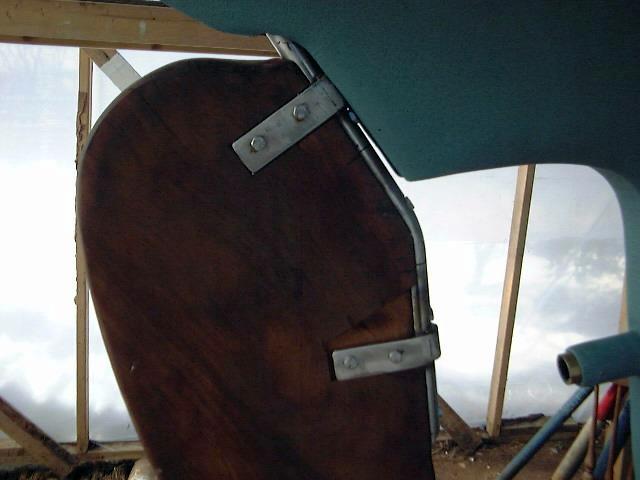
Next, moving outside the boat, I tackled the pintles on the rudder. Made of bronze, these are attached with bolts through the rudder. Removal was pretty easy, after removing the
accumulated paint. I had to spread the straps a little to get them to allow the rudder to pull out, but it was then easy to lift the rudder the 1" or 1-1/2" necessary to free the pintles from the gudgeons.
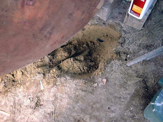
I had to dig a hole beneath the rudder in order to get the rudderpost free of the hull; the hole was about 1' deep or so. This done, the rudder dropped right out.
|
|
 Now, with the rudder in my shop, I began to tackle removing the bronze rudderpost--not absolutely
necessary, but I wanted to replace the ancient screws holding it to the rudder. I think the rudderpost is still in good enough condition to reuse, at least for a while, but we'll see once I clean it up. There is some scoring where it rubbed against the upper bearing. Now, with the rudder in my shop, I began to tackle removing the bronze rudderpost--not absolutely
necessary, but I wanted to replace the ancient screws holding it to the rudder. I think the rudderpost is still in good enough condition to reuse, at least for a while, but we'll see once I clean it up. There is some scoring where it rubbed against the upper bearing.
Removal was easier said than done! There are four large lags securing the rudderpost to the rudder, made of bronze. After cleaning most of the caked paint out of the slots, a large screwdriver took care of the middle two screws without too much trouble. The bottommost screw was loose and turning, but wouldn't back out. I clamped some vice grips on the head and was able to pull it out--turns out it isn't a screw, but a bolt, about 6" long! (with no nut, just kind of stuck in the hole.
Hmmm..).
|
|
 The top screw
turned out to be a real pain. I couldn't get it to turn with my biggest screwdrivers, and
there was no way yet to clamp vice grips on the head. I finally got it to release its grip by loosening all around the head with an awl and an old chisel, and finally prying the fastener out enough to grab it with the vice grips. Surprise! The top one is also a bolt. I haven't figured out the logic here, as there seems to be no signs of nuts or mortises in the body of the rudder to accept nuts. The top screw
turned out to be a real pain. I couldn't get it to turn with my biggest screwdrivers, and
there was no way yet to clamp vice grips on the head. I finally got it to release its grip by loosening all around the head with an awl and an old chisel, and finally prying the fastener out enough to grab it with the vice grips. Surprise! The top one is also a bolt. I haven't figured out the logic here, as there seems to be no signs of nuts or mortises in the body of the rudder to accept nuts.
|
|
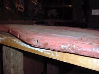
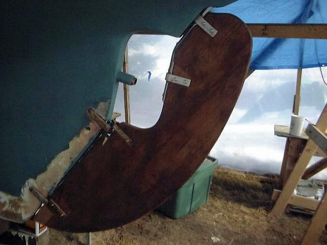
 The body of the rudder is in good condition, with no checking or uneven drying, and no signs of gaps between the individual planks. It has never been sheathed in fiberglass, nor will it be. All that is required is to do a little scraping and sanding to remove the old paint, and we'll be back in business--at least once I repair the bottom with a dutchman. The body of the rudder is in good condition, with no checking or uneven drying, and no signs of gaps between the individual planks. It has never been sheathed in fiberglass, nor will it be. All that is required is to do a little scraping and sanding to remove the old paint, and we'll be back in business--at least once I repair the bottom with a dutchman.
|
|
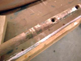 Well, unfortunately things don't look so good for the rudderpost. I sanded the dirt and oxidation off down to bright metal, and there is a fair bit of bronze with a pinkish hew--signs of electrolysis and who-know-how much metal damage. There is also bad scoring where the rudderpost rubbed against the top and bottom of the fiberglass tube in the cockpit. The bearings apparently hadn't been doing their job for some time. I may need to replace the rudderpost--which can't be a cheap
item, of course. Read on for more details. Well, unfortunately things don't look so good for the rudderpost. I sanded the dirt and oxidation off down to bright metal, and there is a fair bit of bronze with a pinkish hew--signs of electrolysis and who-know-how much metal damage. There is also bad scoring where the rudderpost rubbed against the top and bottom of the fiberglass tube in the cockpit. The bearings apparently hadn't been doing their job for some time. I may need to replace the rudderpost--which can't be a cheap
item, of course. Read on for more details.
|
|
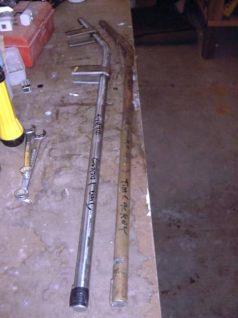
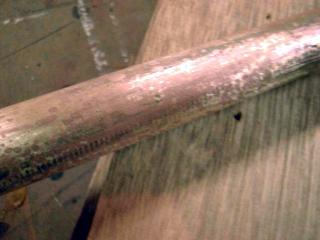 These photos show the rudderpost after sanding and cleaning. You can see the pinkish tinge in contrast to the bright bronze. These photos show the rudderpost after sanding and cleaning. You can see the pinkish tinge in contrast to the bright bronze.
|
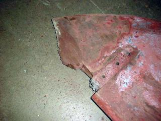
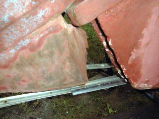
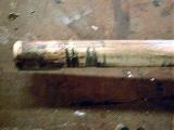
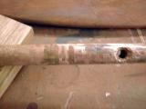
| The rudderpost is scored rather
badly in the two places it rubbed against the rudder tube. The photo
(left) shows the top end of the post and the deep scoring there; the photo
(right) shows scoring just above the first bolthole at the top of the
rudder. Update! New rudderpost
ordered. See
below. |
|
|
|
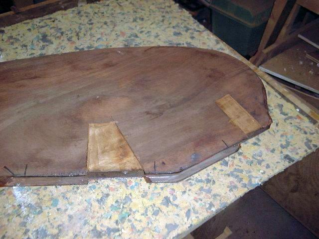
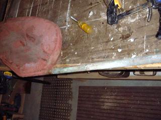
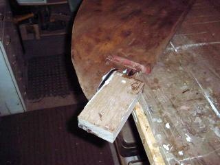
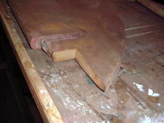 I cut a nice straight chunk out of the bottom of the rudder, removing the broken edges that had been there (see photo at top of page). The next step was to laminate two 3/4" pieces of mahogany together with epoxy to achieve the proper thickness (since I don't have any mahogany that is the same thickness as the leading edge of the rudder, about 1 1/4"). I let the block cure overnight before continuing. I cut a nice straight chunk out of the bottom of the rudder, removing the broken edges that had been there (see photo at top of page). The next step was to laminate two 3/4" pieces of mahogany together with epoxy to achieve the proper thickness (since I don't have any mahogany that is the same thickness as the leading edge of the rudder, about 1 1/4"). I let the block cure overnight before continuing.
I also scraped and sanded all the old paint off the rudder. As originally thought, the wood is in good
condition and the bulk of the rudder will require no work.
|
|
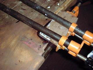 Once the laminated block of mahogany was cured, I unclamped it and ran one edge through my jointer to flatten and square it. I then trimmed the opposite edge on the table saw to allow for a flat surface for the clamps, and trimmed one short end so it was flat and square with the jointed edge. This done, I cleaned the mating surfaces of the block and the rudder with acetone, and mixed up a batch of epoxy thickened with cabosil to a non-sagging consistency (peanut butter). With this mixture spread heavily on both pieces, I clamped the new section to the rudder. Because of the curve of the rudder, there was no way to clamp against itself, so I screwed the rudder to the bench through the pintle boltholes, and clamped against the opposite side of the bench. Once the laminated block of mahogany was cured, I unclamped it and ran one edge through my jointer to flatten and square it. I then trimmed the opposite edge on the table saw to allow for a flat surface for the clamps, and trimmed one short end so it was flat and square with the jointed edge. This done, I cleaned the mating surfaces of the block and the rudder with acetone, and mixed up a batch of epoxy thickened with cabosil to a non-sagging consistency (peanut butter). With this mixture spread heavily on both pieces, I clamped the new section to the rudder. Because of the curve of the rudder, there was no way to clamp against itself, so I screwed the rudder to the bench through the pintle boltholes, and clamped against the opposite side of the bench.
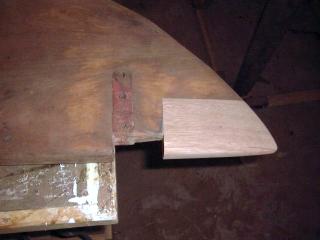
I left the clamps on overnight. When the epoxy was kicked, I began to fair the new piece to the rudder shape by cutting the basic shape with a jigsaw and circular saw. Then, with a belt sander, I rough-shaped the block to close to the final contours of the rudder.
|
|
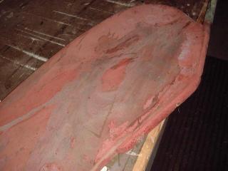
 Finally, with a random orbit sander, I finished off the shaping of the new section, carefully fairing it in with the surrounding rudder and tapering it in two directions--towards the trailing edge and towards the bottom tip. I also rounded over the leading edge to match the rest of the rudder. Finally, with a random orbit sander, I finished off the shaping of the new section, carefully fairing it in with the surrounding rudder and tapering it in two directions--towards the trailing edge and towards the bottom tip. I also rounded over the leading edge to match the rest of the rudder.
|
 |
 |
Work remaining on the rudder is pretty much limited to cleaning up the mortises for the pintles, and filling and redrilling the pintle boltholes. Plus, I have to deal with the rudderpost. I may also look into possibly adding some bushings in the gudgeons, and I need to add bearings to the rudder tube.
Update!
 I ordered a new stainless rudder shaft from
H&H Propeller, made to match the old one exactly. I thought about
having some ears welded on, which would extend back onto the rudder and allow
the shaft to be throughbolted. For some reason, I either forgot or put it
off when I dropped off the shaft. A couple weeks later, in a fortuitous
moment, I received a call from the machinist with a question about the shaft,
and I was able to tell him the details for the stainless ears that I
wanted. After another week or so, the shaft was ready for pickup. I ordered a new stainless rudder shaft from
H&H Propeller, made to match the old one exactly. I thought about
having some ears welded on, which would extend back onto the rudder and allow
the shaft to be throughbolted. For some reason, I either forgot or put it
off when I dropped off the shaft. A couple weeks later, in a fortuitous
moment, I received a call from the machinist with a question about the shaft,
and I was able to tell him the details for the stainless ears that I
wanted. After another week or so, the shaft was ready for pickup.
|
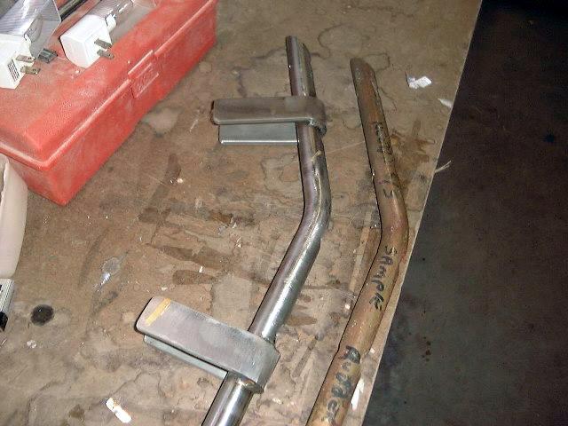
 The
welded ears are located 4" above and below the bend in the shaft, and
extend aft 4". They are not drilled--an oversight on my part.
I'll be sure to enjoy drilling holes through the 1/4" stainless! I
will have to make a shallow mortise for the ears on each side of the rudder,
since they are 1" apart to match the diameter of the shaft. We have
the technology for that, so no problem. The
welded ears are located 4" above and below the bend in the shaft, and
extend aft 4". They are not drilled--an oversight on my part.
I'll be sure to enjoy drilling holes through the 1/4" stainless! I
will have to make a shallow mortise for the ears on each side of the rudder,
since they are 1" apart to match the diameter of the shaft. We have
the technology for that, so no problem. |
|
Before reinstalling the rudder hardware,
however, I filled all the holes, including the original lag and drift pin holes
in the top of the rudder and the pintle holes. I used more thickened epoxy
for this, tamping it into the holes with a screw. A little syringe would
have been nice.
 Before I could secure the new rudderpost to the
rudder, I had to make some mortises for the welded ears. The rudder is
about 1-1/4" thick or so, while the ears, being welded to the 1"
shaft, are 1" apart. Because of the angled rudderpost, the lower
mortise required an angled top edge to allow the ears to slide into the proper
position, since the ears are square to the line of the rudderpost rather than
plumb. I marked the mortise positions, ensuring that everything would line
up properly, and roughed out the bulk of the material with a router, leaving a
small amount at the edges. I cleaned this up with a chisel to the marked
lines. Before I could secure the new rudderpost to the
rudder, I had to make some mortises for the welded ears. The rudder is
about 1-1/4" thick or so, while the ears, being welded to the 1"
shaft, are 1" apart. Because of the angled rudderpost, the lower
mortise required an angled top edge to allow the ears to slide into the proper
position, since the ears are square to the line of the rudderpost rather than
plumb. I marked the mortise positions, ensuring that everything would line
up properly, and roughed out the bulk of the material with a router, leaving a
small amount at the edges. I cleaned this up with a chisel to the marked
lines.
|
|
installed the new rudder
post with 3/8" lag screws through the holes in the rudderpost; these have
hex heads, as the original type used (with bugle heads) does not seem to exist
anymore. However, there's enough clearance around the rudderpost to allow
the use of these lager, and the hex head ends up about halfway into the
counterbores in the rudder shaft. The lags are 5 or 6 inches long; I
forget. I drilled pilot holes, then installed the lags using my electric
impact driver. It sure beats hand screwing or ratcheting!
 With
the four lags installed and the rudderpost securely mounted, I drilled through
the stainless ears and through the rudder for four 5/16" bolts. The
drilling went fairly well, and was nowhere near as tough as I have been worried
about. I used a brand-new, high-strength metal-drilling drill bit. I
secured each ear with two 5/16" bolts. With
the four lags installed and the rudderpost securely mounted, I drilled through
the stainless ears and through the rudder for four 5/16" bolts. The
drilling went fairly well, and was nowhere near as tough as I have been worried
about. I used a brand-new, high-strength metal-drilling drill bit. I
secured each ear with two 5/16" bolts.
|
  Next,
I had to dig a hole beneath the rudder to allow me to slip the shaft up through
the boat. Fortunately, the ground was nice and soft by this point. I
inserted the shaft through the rudder tube, and pushed it up through the
hole. Then, I slipped the pintles onto the front of the rudder slightly
above their actual locations, and pushed them down into place, aligning the pins
as I did. This is not quite as easy as it sounds, but eventually I got
them in. Then, I could redrill through the rudder for the new 5/16"
silicone bronze bolts. I used three bolts in each pintle. (The original pintles
are bronze). Next,
I had to dig a hole beneath the rudder to allow me to slip the shaft up through
the boat. Fortunately, the ground was nice and soft by this point. I
inserted the shaft through the rudder tube, and pushed it up through the
hole. Then, I slipped the pintles onto the front of the rudder slightly
above their actual locations, and pushed them down into place, aligning the pins
as I did. This is not quite as easy as it sounds, but eventually I got
them in. Then, I could redrill through the rudder for the new 5/16"
silicone bronze bolts. I used three bolts in each pintle. (The original pintles
are bronze).
 Then,
I installed the original rudder bearing, a new bearing made of PVC and O-rings,
and the tiller head. All is ready now for the installation of a new tiller
shortly before launching. I painted the rudder with three coats of the
same paint I used on the bottom. Then,
I installed the original rudder bearing, a new bearing made of PVC and O-rings,
and the tiller head. All is ready now for the installation of a new tiller
shortly before launching. I painted the rudder with three coats of the
same paint I used on the bottom.
|
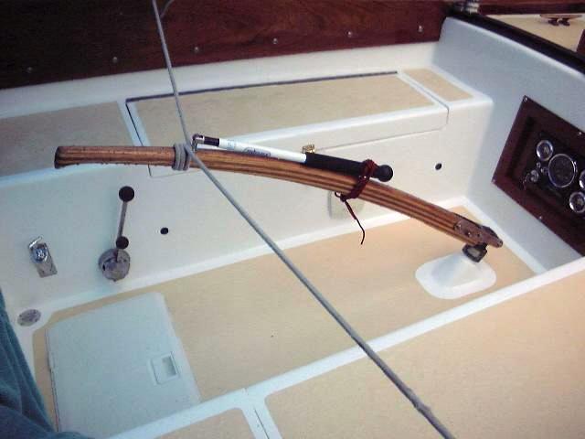 I
bought a stock tiller from Defender. It's a little longer than the
original one, and is made from alternating layers of mahogany and ash. I
had to modify the bottom end a bit--it was too wide--so that it would fit into
the bronze casting that attaches to the tiller head. Then, I sanded the
whole tiller and put on a few more coats of varnish. I installed a
Forespar tiller extension because I like to steer with extensions. I
bought a stock tiller from Defender. It's a little longer than the
original one, and is made from alternating layers of mahogany and ash. I
had to modify the bottom end a bit--it was too wide--so that it would fit into
the bronze casting that attaches to the tiller head. Then, I sanded the
whole tiller and put on a few more coats of varnish. I installed a
Forespar tiller extension because I like to steer with extensions.
|
|