|
Yanmar 2GM20F:
Templating and Foundation Modifications
This page was last updated on 2
August 2001.
TUESDAY 7/31/01
 Bright
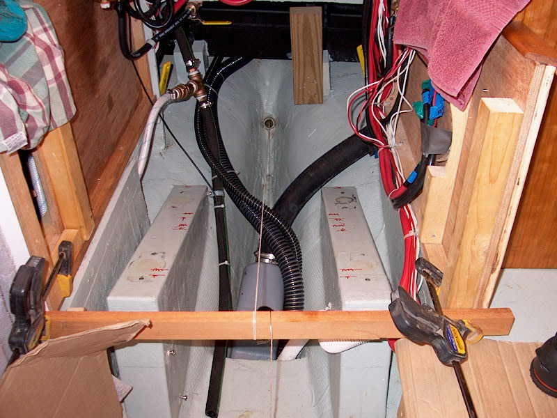
and early the day after hauling and removing the old engine, I was back on the job. The first thing to do was to rig up a
string through the center of the stern tube--the string represents the center of
the propeller shaft, which is the most critical measurement when installing an
engine. I passed a string through the tube from inside, and tied it to a
pencil, which I then taped across the exterior of the opening--attempting to get
it dead center, but I'll come back to it later to be sure. Moving back
inside, I drew the string up tight, and secured it to a board that spanned
across the front of the engine box. I moved the string and board around
until I could visually see that the string was passing through the center of the
stern tube. I went back outside and checked the pencil, and made some
small adjustments now that the string was under tension from the inside.
Then, I checked it again from the inside. Perfect. Bright
and early the day after hauling and removing the old engine, I was back on the job. The first thing to do was to rig up a
string through the center of the stern tube--the string represents the center of
the propeller shaft, which is the most critical measurement when installing an
engine. I passed a string through the tube from inside, and tied it to a
pencil, which I then taped across the exterior of the opening--attempting to get
it dead center, but I'll come back to it later to be sure. Moving back
inside, I drew the string up tight, and secured it to a board that spanned
across the front of the engine box. I moved the string and board around
until I could visually see that the string was passing through the center of the
stern tube. I went back outside and checked the pencil, and made some
small adjustments now that the string was under tension from the inside.
Then, I checked it again from the inside. Perfect.
Next, I placed the engine
template on the beds, passing the string through the holes in the template
projections. Just before doing this, I adjusted the flexible mounts so
that they were approximately in the middle of their range, which would allow me
the freedom to make adjustments in any direction. Immediately, it was
obvious that my calculations were right--I'd have to raise the engine beds
somewhat. That's easy--I'm just glad I didn't have to cut them down, or
change them altogether. Raising the template a little by hand, I estimated
that 3/4" would be a bout perfect. I left the boatyard to go home and
search my scrap pile for some suitable oak to do the job. I found just
enough, and milled two pieces to 3" x 23" to fit the existing beds.
|
|
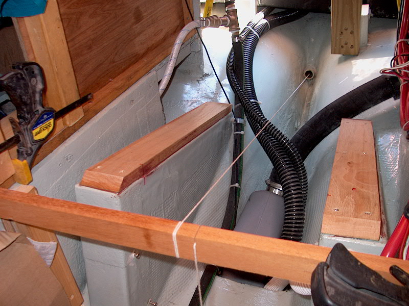 My
plan was to epoxy the boards in place, and to hold them temporarily with
screws to allow me to continue working while the epoxy set up. Plus, the
lags that secure the engine mounts will pass through the oak, further securing
it. The oak strips are really just shims--the structure of the foundation is
already in place. Transferring my marks that I made after removing the old
engine to the sides of the foundation, I sanded the paint off the tops to give
the epoxy a good surface to bond to. Then, I cleaned both surfaces with
Acetone, mixed up a thick epoxy mixture, applied it to the bottoms of the
boards, and screwed the oak pieces into place. I cleaned up the goop that
squeezed out, and I was ready to continue. My
plan was to epoxy the boards in place, and to hold them temporarily with
screws to allow me to continue working while the epoxy set up. Plus, the
lags that secure the engine mounts will pass through the oak, further securing
it. The oak strips are really just shims--the structure of the foundation is
already in place. Transferring my marks that I made after removing the old
engine to the sides of the foundation, I sanded the paint off the tops to give
the epoxy a good surface to bond to. Then, I cleaned both surfaces with
Acetone, mixed up a thick epoxy mixture, applied it to the bottoms of the
boards, and screwed the oak pieces into place. I cleaned up the goop that
squeezed out, and I was ready to continue.
|
|
 Setting the alignment template back on top of the
new oak shims and lining it up with my marks, I could see that now I just had to
make some minor adjustments to the nuts on the flexible engine mounts. The
forward end was sitting a little too low, and the aft end a touch too
high. I made the appropriate adjustments, and the string came nicely into
place through the center of
each hole in the template extensions. If anything, I left the adjustment a
little high, since the manual states that the engine should compress the mounts
by about 3.5mm when it is installed. Setting the alignment template back on top of the
new oak shims and lining it up with my marks, I could see that now I just had to
make some minor adjustments to the nuts on the flexible engine mounts. The
forward end was sitting a little too low, and the aft end a touch too
high. I made the appropriate adjustments, and the string came nicely into
place through the center of
each hole in the template extensions. If anything, I left the adjustment a
little high, since the manual states that the engine should compress the mounts
by about 3.5mm when it is installed.
With my final adjustments made, I ensured that
the template was properly lined up with the fore and aft marks I made earlier
(to ensure that the existing shaft would properly mate with the new transmission
coupling) and then marked the boltholes that would secure the mounts to the
foundation. Then I removed the template and drilled pilot holes for the
lags screws that will hold the mounts in place when I install the engine.
I labeled each mount for its location as well, since the adjustments on each are
slightly different--they need to go in the proper places on the engine in order
to keep my pre-alignment perfect.
|
| Before proceeding, I reinstalled the stuffing box
and slid the shaft in from the inside--remember, the coupling is still
installed. I pushed the shaft as far aft as possible to keep it out of the
way. With that done, it was time to hoist the new engine into the
boat.
Click here to continue. |
|