|
Yanmar SB12
Installation: Engine Foundation
|
|
This page was last
updated on 23 May 2000.
|
|
With the template constructed, I spent some time roughly
positioning the "engine" in the boat. I have an old shaft and
coupling, so I was able to use this to figure out about where the engine should
be placed. There are many considerations, including the height and depth
of the engine, access for inspection and service, and leaving space for the
exhaust system. The new engine will be mounted farther forward than the
Atomic 4, which is necessary because of the height of the head and the depth of
the transmission housing. However, this location will actually provide
better, easier access for servicing, and should work out well. Despite the
new location, it will not encroach too far into the cabin, not much, if any,
forward of the old cabin step that was originally installed at the base of the
ladder.
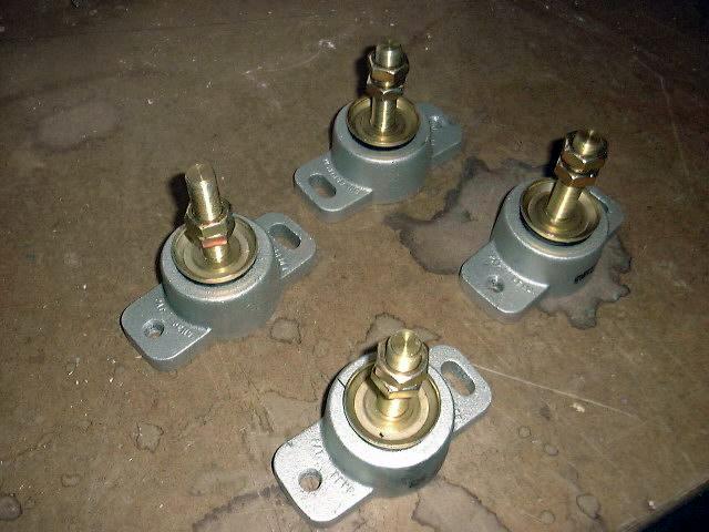 I
purchased some vibration damping, adjustable engine mounts from Hamilton
Marine. Not only do I want the shock absorbing qualities of these
mounts, I also want the adjustability when it comes time to do the final engine
alignment. These will make it much easier. A pair of lock nuts on
each stud allows a fair bit of up and down movement. Because the mounts
add about 3" to the overall height of the engine, I had to take this
into account on my engine template. I cut some pieces of 2x4 to 3"
long and attached them to the bottom of the template; the bottoms of these new
"feet" now become the new bottom of the engine for placement purposes. I
purchased some vibration damping, adjustable engine mounts from Hamilton
Marine. Not only do I want the shock absorbing qualities of these
mounts, I also want the adjustability when it comes time to do the final engine
alignment. These will make it much easier. A pair of lock nuts on
each stud allows a fair bit of up and down movement. Because the mounts
add about 3" to the overall height of the engine, I had to take this
into account on my engine template. I cut some pieces of 2x4 to 3"
long and attached them to the bottom of the template; the bottoms of these new
"feet" now become the new bottom of the engine for placement purposes.
|
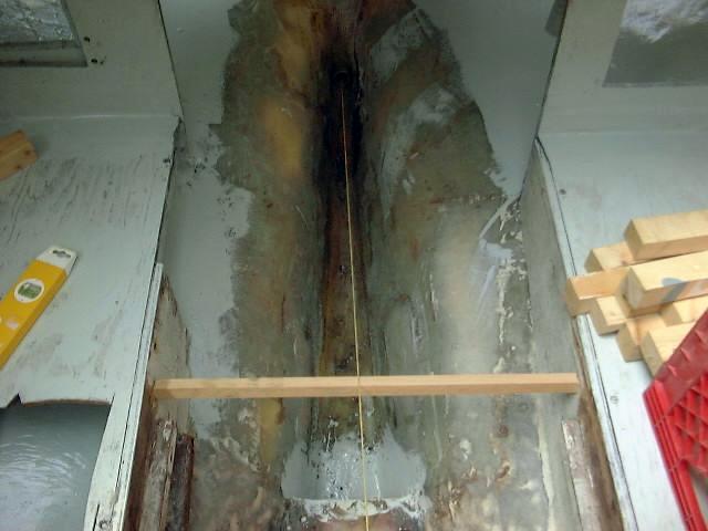
Next, I rigged up an alignment string through
the shaft log. I attached the string over a couple boards, one at each
end, in which I cut a slot to hold the string. I rigged up a ladder
outside the boat to hold the aft 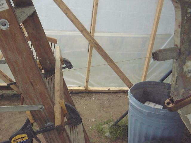 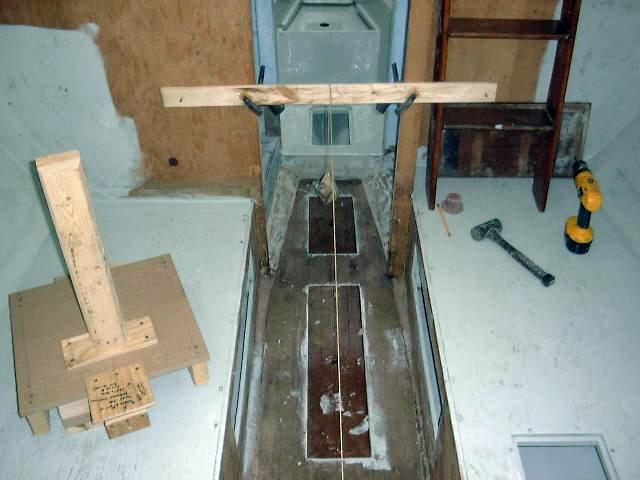 end of the string, and clamped the board at
the forward end of the string to the main bulkhead in the cabin. By moving
the boards up and down and side to side, I was able to center the string in the
stern tube at both ends. This took a lot of back and forth between the
inside of the boat and the ground, but finally the string appeared
centered. This string represents the exact center of the propeller shaft
and, therefore, the transmission coupling, and is a very critical piece of the
alignment and positioning puzzle. As you may recall, when I built the
template I included holes at the exact measurement of the coupling center, and
it is through these holes that the string must pass in order to guarantee proper
alignment and angle. end of the string, and clamped the board at
the forward end of the string to the main bulkhead in the cabin. By moving
the boards up and down and side to side, I was able to center the string in the
stern tube at both ends. This took a lot of back and forth between the
inside of the boat and the ground, but finally the string appeared
centered. This string represents the exact center of the propeller shaft
and, therefore, the transmission coupling, and is a very critical piece of the
alignment and positioning puzzle. As you may recall, when I built the
template I included holes at the exact measurement of the coupling center, and
it is through these holes that the string must pass in order to guarantee proper
alignment and angle. |
|
 I am being very methodical in my approach to
this engine installation. I have never done one before, and obviously want
it to be right in the end. However, I also want each step to go according
to plan, so I take my time and spend a lot of time just looking at the situation
and envisioning the placement of the engine, and scratching my head while I
think of the next move. I am being very methodical in my approach to
this engine installation. I have never done one before, and obviously want
it to be right in the end. However, I also want each step to go according
to plan, so I take my time and spend a lot of time just looking at the situation
and envisioning the placement of the engine, and scratching my head while I
think of the next move.
|
|
 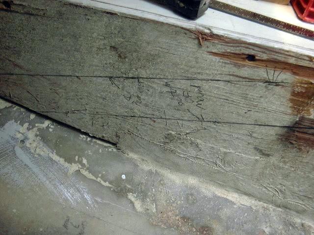 Next,
it was time to transfer the shaft line to the boat somehow. To do this, I
cut a narrow board to a friction fit between the two settee supports (first
picture, left), and, using a level and measuring tape, transferred the position
of the string to the sides of the boat (second picture, left). The top
line represents the center of the shaft. To indicate the bottom of the
adjustable engine mounts, I drew parallel lines 2 3/8" below the center of
the shaft. I determined this distance by measuring the height of the
mounts-- 3" with the adjusting nuts about halfway through their potential
travel (which will allow a good amount of up or down adjustment as necessary)
and subtracting the offset of the center of the shaft from the bottom of the
fixed engine mounts (5/8"). This second line will be the ultimate
final height of the engine foundations. Next,
it was time to transfer the shaft line to the boat somehow. To do this, I
cut a narrow board to a friction fit between the two settee supports (first
picture, left), and, using a level and measuring tape, transferred the position
of the string to the sides of the boat (second picture, left). The top
line represents the center of the shaft. To indicate the bottom of the
adjustable engine mounts, I drew parallel lines 2 3/8" below the center of
the shaft. I determined this distance by measuring the height of the
mounts-- 3" with the adjusting nuts about halfway through their potential
travel (which will allow a good amount of up or down adjustment as necessary)
and subtracting the offset of the center of the shaft from the bottom of the
fixed engine mounts (5/8"). This second line will be the ultimate
final height of the engine foundations.
Phew. There is a lot to this, and I'm
only just beginning!
|
|
 Next,
I wanted to accomplish two important things: to check my calculations and
line transfer (using the engine template I built earlier); and to come up with a
way to easily measure and visualize the size, shape and position of the engine
foundation. Next,
I wanted to accomplish two important things: to check my calculations and
line transfer (using the engine template I built earlier); and to come up with a
way to easily measure and visualize the size, shape and position of the engine
foundation.
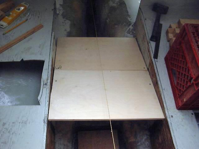
To do this, I screwed cleats to the sides of
the settees, and attached two pieces of scrap plywood (left) to them so that the
top of the plywood was equal to the second line--the bottom of the flexible
engine mounts. This simple platform would allow me to place my engine
template on it, thus holding it in approximately the correct position and
orientation to the shaft string.
|
|
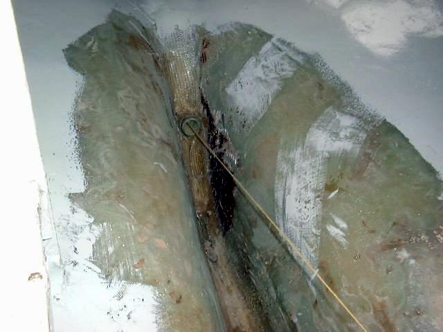
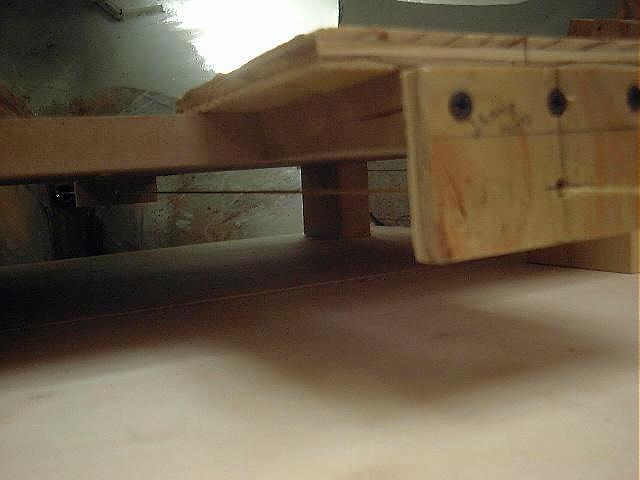
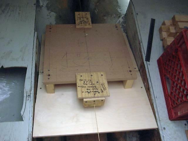 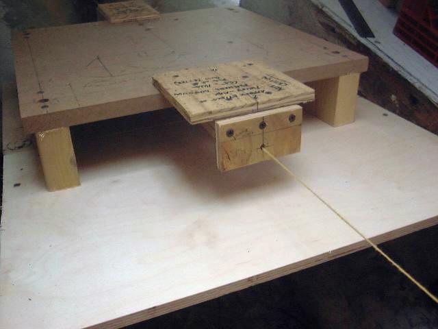 By
placing my template on top of the platform, and running the alignment string
through the holes I had positioned for this purpose, I could see that my rough
transfer of the shaft line had been pretty accurate. I was able to
slightly adjust the heights of the cleats to level the platform, bringing the
template into the proper position relative to the alignment string. Once
everything seemed placed in the proper manner, I traced a line at the top of the
platform to the settees, which will now serve as the absolute top of the new
foundation. The picture below shows a close-up of the alignment string
running through both of the shaft holes in the template, and then on to the
stern tube. By
placing my template on top of the platform, and running the alignment string
through the holes I had positioned for this purpose, I could see that my rough
transfer of the shaft line had been pretty accurate. I was able to
slightly adjust the heights of the cleats to level the platform, bringing the
template into the proper position relative to the alignment string. Once
everything seemed placed in the proper manner, I traced a line at the top of the
platform to the settees, which will now serve as the absolute top of the new
foundation. The picture below shows a close-up of the alignment string
running through both of the shaft holes in the template, and then on to the
stern tube.
|
|
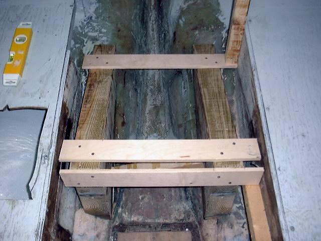
 Now,
on to the problem of sizing and building the actual foundation: to make
this process easier, I removed the platform and cleats and repositioned them so
that the bottom of the plywood platform now equaled the line of the top
of the foundation. Thusly positioned, I could now measure from beneath the
platform to the hull and determine the size of the foundation. I had
previously marked the rough centerlines of the mounting holes and edge of the
mounts on the hull (by just placing my template on the hull and transferring the
marks), so I could fairly accurately size the foundation. Now,
on to the problem of sizing and building the actual foundation: to make
this process easier, I removed the platform and cleats and repositioned them so
that the bottom of the plywood platform now equaled the line of the top
of the foundation. Thusly positioned, I could now measure from beneath the
platform to the hull and determine the size of the foundation. I had
previously marked the rough centerlines of the mounting holes and edge of the
mounts on the hull (by just placing my template on the hull and transferring the
marks), so I could fairly accurately size the foundation.
Using the marked rough mount centerlines on
the hull as a guide, I measured out 1 3/4" in each direction to show the
approximate limits of the yet-to-be built wooden foundation, which is to be
constructed of 3 1/2" thick solid lumber. Then, at four different
places--the inside and outside of the proposed foundation at the forward and
after ends of the area--I measured the height from the hull to the bottom of my
template. The bottoms of the foundation will require a steep angle in
order to fit the shape of the hull, which is sharply curved in the area where
the foundation is to be installed. The measurements between the inside and
outside of the mount varied by about 2 1/2" over the 3 1/2" width of
the foundation.
Next, I glued up a pair of blanks out of solid
southern yellow pine lumber to make up the full height required at the front of
the foundation--over 12 1/2". I glued three pieces of 4x6 lumber
together in order to make up the total height. After letting the epoxy
cure overnight, I laid out the inside and outside dimensions I measured in the
boat on the blanks, and cut off the waste with a circular saw set to
approximately the right angle. I had to cut from both sides of the blank
because of its thickness; any unevenness I sanded out with a belt sander.
With the rough foundations cut, I spent quite
a lot of time running back and forth between the boat and my garage workshop,
carefully fitting the foundation to the hull as necessary to bring the top of it
up or down to the proper level, dictated by the marks I had made previously
inside the boat. This was a total trial and error process, which,
fortunately, did not result in any errors--just trials! Once the pieces
were properly shaped--I did all the final shaping with the belt sander--I was
ready to install them in the boat. First, though, I sanded them to remove
excess epoxy from the outside of the glue joints, and rounded over the top and
front edges with a router to promote better adhesion of the fiberglass overlay
that will be installed later.
Now to install one piece at a time:
Because of the angle of the hull, there is no way these pieces would stay in
place without some support. Before getting into epoxy, I carefully
positioned the starboard mount where it needed to be and attached some scraps of
2x4 with screws to hold it in the proper position. After marking the
location of these braces on the foundation, I removed them and readied the area
for epoxy.
|
|
 I
mixed up some thick West System (thickened with #406) and glopped it heavily on
the hull beneath the foundation, especially at the forward end, which is
elevated somewhat. Then, I positioned the foundation and attached the
various braces, and cleaned up any extra epoxy that squeezed out. I let
this cure overnight. I decided to install the second piece the next day, since
it would be more convenient to use the first (starboard) foundation to properly
position the port side. I
mixed up some thick West System (thickened with #406) and glopped it heavily on
the hull beneath the foundation, especially at the forward end, which is
elevated somewhat. Then, I positioned the foundation and attached the
various braces, and cleaned up any extra epoxy that squeezed out. I let
this cure overnight. I decided to install the second piece the next day, since
it would be more convenient to use the first (starboard) foundation to properly
position the port side.
The next day the epoxy was cured, and the
mount was firmly affixed to the hull. I removed the temporary braces, and,
using the first side as a guide, positioned the port foundation in place and
constructed some temporary bracing to hold it there once the epoxy was
installed. Then, I followed the same procedure to epoxy the port side in
place as I used on the starboard side, and braced it in place.
When the epoxy kicked, I ground
flush any areas that protruded beyond the base of the foundations in preparation
for fiberglassing. Next, I cut some fiberglass cloth to size for the
tabbing--three layers of 24 oz. woven roving on each side of the foundations,
with two layers of lighter cloth to cover the tops and ends. The roving is
the main structural component, and will securely and permanently attach the
foundations to the hull, while the lighter cloth is not needed for structural
purposes and is intended only to completely encapsulate the wood in
fiberglass. I also cut some narrow strips of mat to use over the edges of
the heavier roving, which will present a smoother appearance once all is said
and done.
After thoroughly cleaning the
entire area with acetone, again, I wet out the fabric and rolled it into
place. Experience has taught me that the best way to handle this sort of
installation is to wet out the three layers of cloth on a flat surface, then to
transfer them to their final location and roll them out with an air
roller--rather than attempt to wet them out in place. Getting the cloth
into place on the outboard sides of the foundations was tricky and very
messy--it's a tight fit, as you can tell from the photos--but the process
basically went very well. I did one side of the boat at a time, starting
with the outboard tabbing on the starboard side. Once the heavy tabbing
was in place on both edges of the starboard side, I installed the lighter cloth
overlay on the top and ends of the foundation; these pieces also overlapped the
tops of the tabbing on the sides, covering the rough roving edges and fully
encapsulating the wood. I added some of the strips of mat where needed to
make the final installation neater. I carefully rolled everything out to
rid the laminate of any air pockets, etc. It was a fairly cool day, so I
had a decent amount of time to work with the epoxy resin.
|
|
Once the starboard side was done,
I repeated the process on the port side, which was a little easier since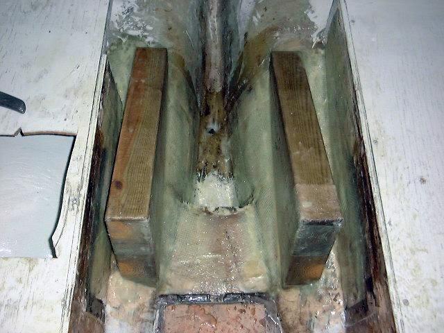 there is more clearance between the foundation and the settee on the port
side. One of the interesting things I have found out about the boat during
the layout of the engine foundations is how asymmetrical everything is.
For example, the settees look like they extend the same distance towards the
centerline, but they do not--the starboard side comes out over an inch
farther. Also, the aftermost bulkhead, behind the galley, is not at all
square or even aligned; the port side is mounted considerably farther forward
than the starboard. Don't count on the placement of these fixed structural
members if you ever attempt a similar project on your boat.
there is more clearance between the foundation and the settee on the port
side. One of the interesting things I have found out about the boat during
the layout of the engine foundations is how asymmetrical everything is.
For example, the settees look like they extend the same distance towards the
centerline, but they do not--the starboard side comes out over an inch
farther. Also, the aftermost bulkhead, behind the galley, is not at all
square or even aligned; the port side is mounted considerably farther forward
than the starboard. Don't count on the placement of these fixed structural
members if you ever attempt a similar project on your boat.
Doing this fiberglass work brings
back memories of my time as a laminator at The Hinckley Company, which is where
I learned most of the basic fiberglass skills I have used so far in this
project. Laminating is a dirty, nasty job at best; at least, because I was
using epoxy resin, there were no harsh styrene fumes to deal with.
|
|
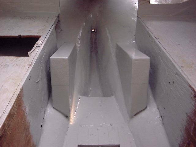 With the laminating done, the
foundations for the new engine were complete. With the laminating done, the
foundations for the new engine were complete.
After a quick sanding to provide
a little tooth and to smooth over any rough areas, I applied two coats of gray
Interlux Bilgekote paint, which I have been using throughout the interior of the
boat. It's a nice clean color, and will help protect the bilge in the
engine room from absorbing grease or oil. It will also be easier to keep
clean.
With the painting complete, it
was time to move on to the final placement of the engine mounts and the
installation of the engine.
|
|
|
Continue to Step
3--Installing the Engine
|
|