|
Mast Support Beam Replacement
This page was last updated
on 26 November 2003.
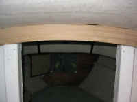
 Given
my worries about the mast support in general, and the repairs required
to the deck, it was only natural that I decided to inspect--and
remove--the existing mast support beam, which was original to the boat.
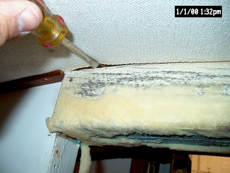
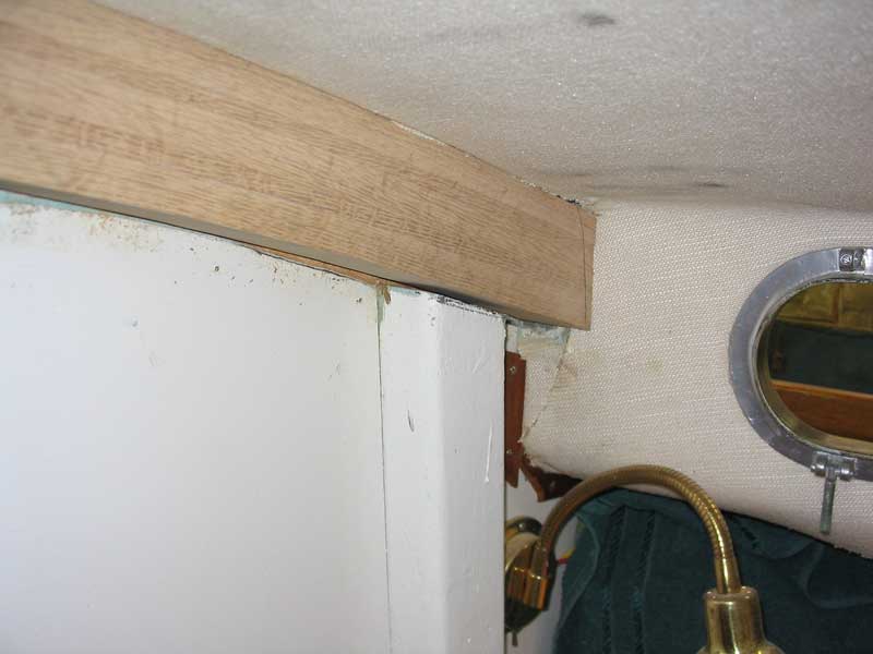
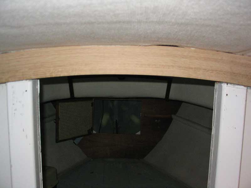
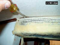
Removal involved removing several pieces of wooden trim, which were screwed in
place, and then the glued-on fabric over the beam.
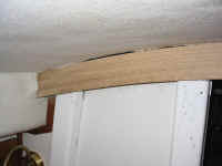
It was obvious that there had been movement in the center portion,
especially in the forward add-on piece. There was a gap between
the beam and the bottom skin, and there was still room to hike the thing
upwards. The beam itself, however, was still in decent shape--the
same as before, so I wasn't sure initially how I was going to handle
is: reinforce, or build new. My initial thoughts were to
reinforce the beam with some metal plates, as this would avoid the need
to delve too deeply into the finished surfaces surrounding the
beam. On further inspection, though, it looked like the beam would
come out easily, if I could removed two small sections of tabbing and
cut the heads off a series of bolts passing through the forward
bulkhead. Given
my worries about the mast support in general, and the repairs required
to the deck, it was only natural that I decided to inspect--and
remove--the existing mast support beam, which was original to the boat.
Removal involved removing several pieces of wooden trim, which were screwed in
place, and then the glued-on fabric over the beam.
It was obvious that there had been movement in the center portion,
especially in the forward add-on piece. There was a gap between
the beam and the bottom skin, and there was still room to hike the thing
upwards. The beam itself, however, was still in decent shape--the
same as before, so I wasn't sure initially how I was going to handle
is: reinforce, or build new. My initial thoughts were to
reinforce the beam with some metal plates, as this would avoid the need
to delve too deeply into the finished surfaces surrounding the
beam. On further inspection, though, it looked like the beam would
come out easily, if I could removed two small sections of tabbing and
cut the heads off a series of bolts passing through the forward
bulkhead.
|
|
|
|
The next day, I attacked the beam
removal. It all started out well enough. First, I installed
a spiral bit in my Dremel tool, and easily cut through the tabbing on
each end of the beam. Then, with a cutting wheel in my 4-1/2"
grinder, I buzzed off the nuts securing the bolts running through the
beam; the heads were hidden in the vee berth behind the Formica bulkhead
covering, so I didn't want to try and re move them traditionally, as I
hoped to not disrupt the Formica. Cutting the nuts off released
the add-on section of the beam in the forward part of the passageway to
the vee berth, so I removed that section. Then I made
attempts to pry the beam out of position, which should have been
easy.
 No luck--it barely
budged, though it moved enough that it seemed there was nothing serious
holding it in position. Thinking logically that the wood was
still gripping the4 or 5 bolts passing through the beam (even with the
nuts removed), I used a drill to ream the wood out around the bolts,
which should have released the beam. Still, I couldn't get the
beam to come out. I tried several approaches to no avail, and the
job rapidly became infuriating. There was no reason why the beam
shouldn't have come out, or so I thought. After all, I had managed
to pry it a short distance away from the bulkhead on each side, so I
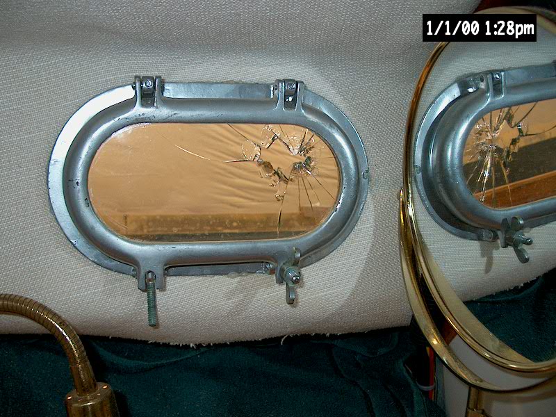
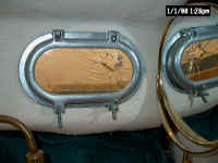
figured there must not be anything really holding it. My mood was
made no better by an unfortunate lack of control with my pry bar at one
point; as nice as can be, the wild end caught the starboard head
porthole and shattered a hole in the glass in the blink of an eye.
I became somewhat more unhappy at this point, and might have spoken a
few harsh words. I can't remember; perhaps you should ask my
neighbors what they heard. No luck--it barely
budged, though it moved enough that it seemed there was nothing serious
holding it in position. Thinking logically that the wood was
still gripping the4 or 5 bolts passing through the beam (even with the
nuts removed), I used a drill to ream the wood out around the bolts,
which should have released the beam. Still, I couldn't get the
beam to come out. I tried several approaches to no avail, and the
job rapidly became infuriating. There was no reason why the beam
shouldn't have come out, or so I thought. After all, I had managed
to pry it a short distance away from the bulkhead on each side, so I
figured there must not be anything really holding it. My mood was
made no better by an unfortunate lack of control with my pry bar at one
point; as nice as can be, the wild end caught the starboard head
porthole and shattered a hole in the glass in the blink of an eye.
I became somewhat more unhappy at this point, and might have spoken a
few harsh words. I can't remember; perhaps you should ask my
neighbors what they heard.
|
|
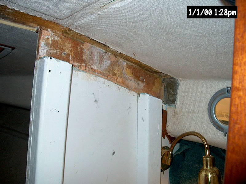
 After much struggle,
accompanied by a not-so-nice-something-is-being-ripped-apart sound, I
finally determined that there were two secret screws (driven from the
forward side of the bulkhead back into the beam, so they were invisible
behind the Formica) holding the beam in place. The ripping sound I
had heard was actually the plywood bulkhead being torn apart as I tried,
unbeknownst to me, to pull the screw the wrong way through the
material. I was less than pleased at this new development, but at
least now it was a cinch to cut the screws with my Sawz-All and release
the beam. It came out easily after that. What a stupid hour
I had spent. But the beam was out, never to return: I
planned to build a new, laminated beam to go in its place. After much struggle,
accompanied by a not-so-nice-something-is-being-ripped-apart sound, I
finally determined that there were two secret screws (driven from the
forward side of the bulkhead back into the beam, so they were invisible
behind the Formica) holding the beam in place. The ripping sound I
had heard was actually the plywood bulkhead being torn apart as I tried,
unbeknownst to me, to pull the screw the wrong way through the
material. I was less than pleased at this new development, but at
least now it was a cinch to cut the screws with my Sawz-All and release
the beam. It came out easily after that. What a stupid hour
I had spent. But the beam was out, never to return: I
planned to build a new, laminated beam to go in its place.
|
|

|
|
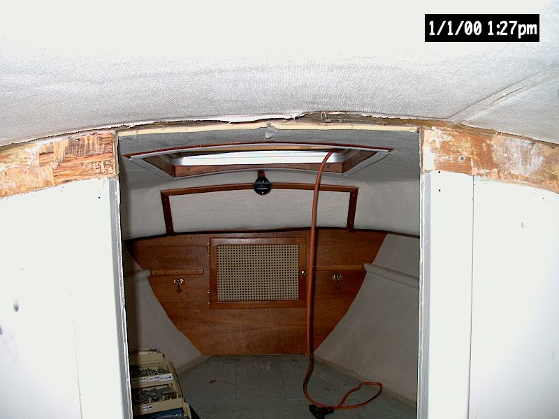
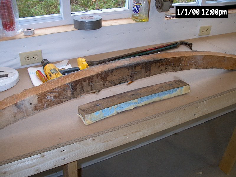
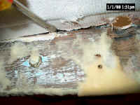
 After cleaning up the
mess in the cabin--dust, splintered wood, and the like--and removing the
broken port, I felt much better, as if things had returned to some
semblance of control. Mass destruction of a finished boat is less
than my favorite thing. With the beam now on my bench, I inspected
it and found that it was in generally good condition, with only minor--and
expected--checks. Still, the sawn beam is inherently prone to some
flattening of the arch when under load, so I felt good about my decision
to build new. I put the beam aside for a week or so while I
concentrated on completing the deck-repair
portion of the mast step project. After cleaning up the
mess in the cabin--dust, splintered wood, and the like--and removing the
broken port, I felt much better, as if things had returned to some
semblance of control. Mass destruction of a finished boat is less
than my favorite thing. With the beam now on my bench, I inspected
it and found that it was in generally good condition, with only minor--and
expected--checks. Still, the sawn beam is inherently prone to some
flattening of the arch when under load, so I felt good about my decision
to build new. I put the beam aside for a week or so while I
concentrated on completing the deck-repair
portion of the mast step project.
|
|

|
|
Building a New Beam
After concentrating on the mast step
reinforcement and deck repairs for a number of days, as well as waiting
for delivery of some lumber with which to fabricate the new beam, I
eventually turned my attention to the issue of constructing a new
beam. I chose to cold mold the new beam out of epoxy-laminated
strips of white oak, which would form a very strong beam resistant to
the forces placed upon it by the mast compression.
 The
white oak lumber I ordered came in the rough state, with a nominal 4/4
dimension. I received two boards, each about 9' in length and
between 7" and 9" wide. I thought I could get all the
material I needed out of the larger of the two boards, so I began with
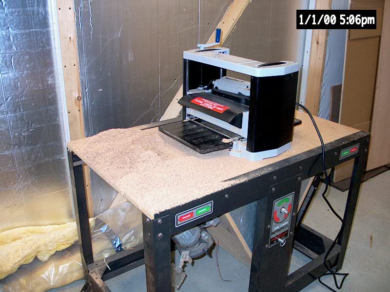
that. The first step was to plane the board smooth on each side,
which reduced its overall thickness to about 3/4". Knowing
how much rough lumber I would be using in the future as I complete
projects on Glissando and also for the construction of the Triton
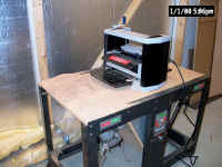
Daysailor, I decided to invest in a small thickness planer rather
than fight with other means of smoothing the boards. I purchased a
12" Delta planer and, in the days before beginning work on the mast
beam, I experimented with the tool to gain some knowledge of its use. The
white oak lumber I ordered came in the rough state, with a nominal 4/4
dimension. I received two boards, each about 9' in length and
between 7" and 9" wide. I thought I could get all the
material I needed out of the larger of the two boards, so I began with
that. The first step was to plane the board smooth on each side,
which reduced its overall thickness to about 3/4". Knowing
how much rough lumber I would be using in the future as I complete
projects on Glissando and also for the construction of the Triton
Daysailor, I decided to invest in a small thickness planer rather
than fight with other means of smoothing the boards. I purchased a
12" Delta planer and, in the days before beginning work on the mast
beam, I experimented with the tool to gain some knowledge of its use.
Planing
was uneventful. Given the hardness of the oak, and the
novelty of the planer to me, I was conservative in how much material I
removed with each pass, so it took a number of passes before the wood
was smooth, flat, and at the proper thickness. I was pleased with
the performance of the planer on the tough white oak. |
|
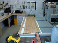
Next, I crosscut the board to make it easier to handle, and to reduce its
length to that which I wanted to use for the new beam. After
measuring the existing beam, and allowing plenty of extra, I cut the board
off at 6' in length. Conveniently, this left more than enough length
in the board to use the short cutoff as the stock for the additional
reinforcing section of the beam that extends forward into the vee berth
from the main beam.
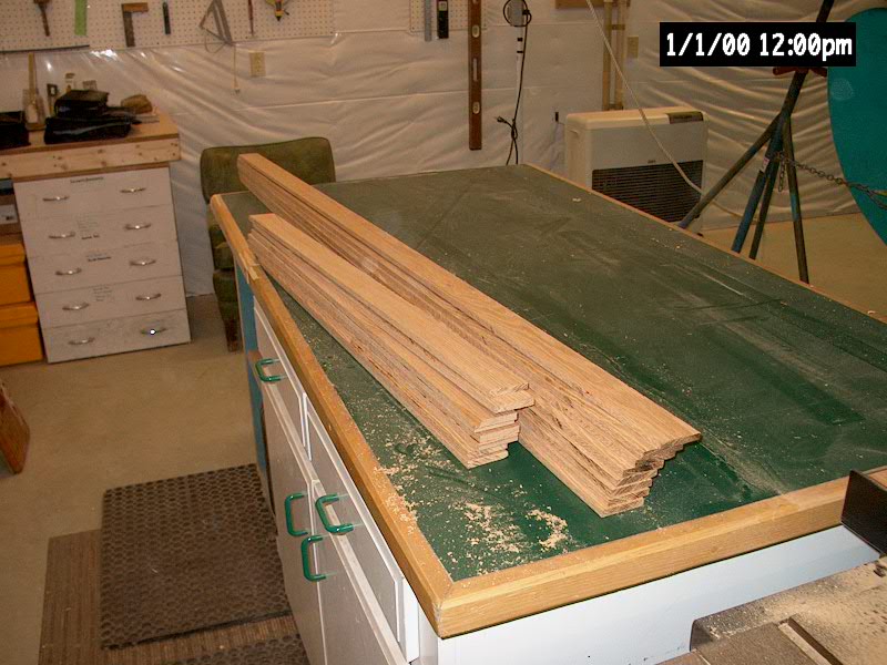
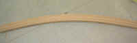
With that done, I turned to
the next task: ripping the board into strips of the proper width and
thickness. The edges of the board were curved, so I set up a long
straightedge and trimmed one edge with a circular saw, being careful to
remove only the minimum amount of wood possible. With one straight
edge, I could begin ripping the board into strips of the proper width for
the new mast beam. The old beam was just about 2" wide, so I
decided to go just over 2" for the new one. At that width, I
managed to rip four strips out of the original board, with only a narrow
piece of waste left over.
|
|
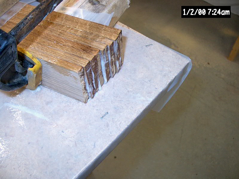
Now I had to resaw each
strip to reduce the thickness of the boards that I would use for the
lamination. I had originally hoped to use boards of about 1/4"
in thickness, which would have given me 12 laminations in the 3"
height of the beam and all but eliminated any appreciable springback after
gluing. However, the original oak board was not thick enough to get
three 1/4" pieces from, and I didn't wish to waste so much material
in order to only get two boards. Instead, I decided to resaw each
strip in half, which gave me new boards of about 3/8" in thickness
with no material left over. I used the table saw to resaw the
boards, and ended up with 8 boards, giving me a total height of the
desired 3". Using a formula for roughly calculating springback,
I determined that with 8 laminations, I could be looking at nearly
1/4" of potential springback after the wood was glued. I would
have to take this into account when constructing the mold.
With the 8 main pieces
milled to the proper dimensions, I continued by milling the shorter
lengths into similarly-dimensioned pieces for later use as the beam
reinforcement as mentioned above.

|
Computing
springback in a curved laminate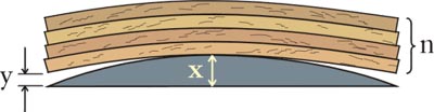
When a strip
of wood, a ply, is bent to a curve and released, it springs back to its
original shape. A stack of loose plies will do the same. When these plies
are glued together while clamped to a curve, they tend to stay curved, but
will straighten out or spring back a little. When building the mold or
form for the laminate its common to make the curve a little tighter to
compensate for the springback. The amount of springback depends on the
number of plies in the laminate, not in the ply material or the ply
thickness. A simple formula can help predict the amount of springback you
can expect:
y
= x/n2
y
= the amount of springback
x = the amount of deflection
n = the number of plies
Thus
with four plies, the springback (y) will be 1/16" if the amount of
deflection (x) is 1". By using plies half the thickness you double
the number of plies for a given thickness of laminate and reduce
springback four times-in this case to 1/64".
Tip
courtesy of West System website.
|
|
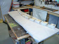
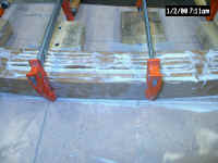
I decided to laminate the
beam on a horizontal mold, rather than a vertical one. Having read
others' experiences with laminating over a saddle-type vertical mold, I
thought it would be more convenient and easier to have the whole mold
built on a flat platform, with the strips oriented on edge. This
would help keep the edges of the strips aligned, would prevent side
slippage, and would prevent epoxy spillout from pouring into the clamps--a
common problem with the other method.
I began with a sheet of
particle board that I had lying around. I ripped it in half and
secured the two pieces together with screws and 2x4 bracing beneath across
the seam, giving me a flat platform of an appropriate width and
length. Having the 2x4s beneath had the added benefit of raising the
platform off the bench, which I thought might come in handy should I need
to clamp the beam in a downward direction during lamination. I laid
the old beam down on the platform and traced its profile directly on the
particle board. Because the old beam was slightly taller on its
aft-facing edge (since the top was beveled to approximate the angle of the
cabin trunk), I chose to trace it in that direction, which would give me
the tallest beam necessary and replicate the largest arc. I marked a
straight baseline and determined the beam centerline, and made the
appropriate marks. With the outline traced, I covered the whole platform
in some 6 mil clear plastic, which would protect it from epoxy and would
also prevent the new beam from sticking once it was glued up.
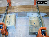
 To
take the potential springback into consideration, I made a new mark at the
centerline of the beam arc, but 1/4" higher. Just beneath this
mark, I screwed a short piece of 2x4. Then, at each end of the beam
tracing, I screwed in another short piece of 2x4, but kept those edges at
the original marks. With the center of the new shape 1/4"
higher, the theory is that the ends will spring up enough when the
material is glued and cured, and will therefore ensure that the beam ends
up with approximately the correct shape and arc. To
take the potential springback into consideration, I made a new mark at the
centerline of the beam arc, but 1/4" higher. Just beneath this
mark, I screwed a short piece of 2x4. Then, at each end of the beam
tracing, I screwed in another short piece of 2x4, but kept those edges at
the original marks. With the center of the new shape 1/4"
higher, the theory is that the ends will spring up enough when the
material is glued and cured, and will therefore ensure that the beam ends
up with approximately the correct shape and arc.
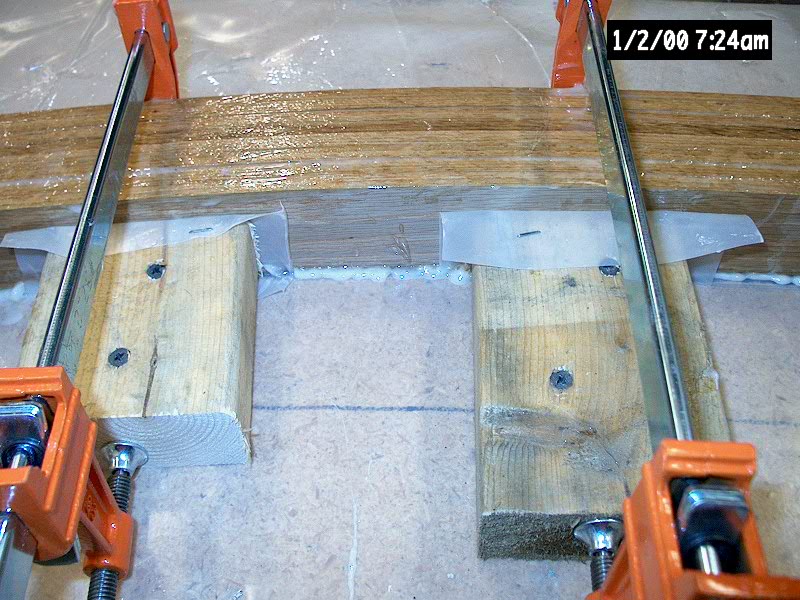
 To
ensure a fair curve and the proper placement of additional clamping
blocks, I bent one of the oak plies around the three main blocks (center
and two ends), and traced its arc on the plastic. Then, I installed
further blocking beneath this line, with blocks located every couple
inches. To complete the mold, I added small pieces of plastic
sheeting over the end of each 2x4 block to prevent the beam lamination
from sticking irrevocably to the mold. I added a final block on each
end well outside the actual end of the beam shape; the arc must continue
past the actual stopping point to ensure that the curve is fair and
smooth. To
ensure a fair curve and the proper placement of additional clamping
blocks, I bent one of the oak plies around the three main blocks (center
and two ends), and traced its arc on the plastic. Then, I installed
further blocking beneath this line, with blocks located every couple
inches. To complete the mold, I added small pieces of plastic
sheeting over the end of each 2x4 block to prevent the beam lamination
from sticking irrevocably to the mold. I added a final block on each
end well outside the actual end of the beam shape; the arc must continue
past the actual stopping point to ensure that the curve is fair and
smooth.
|
|
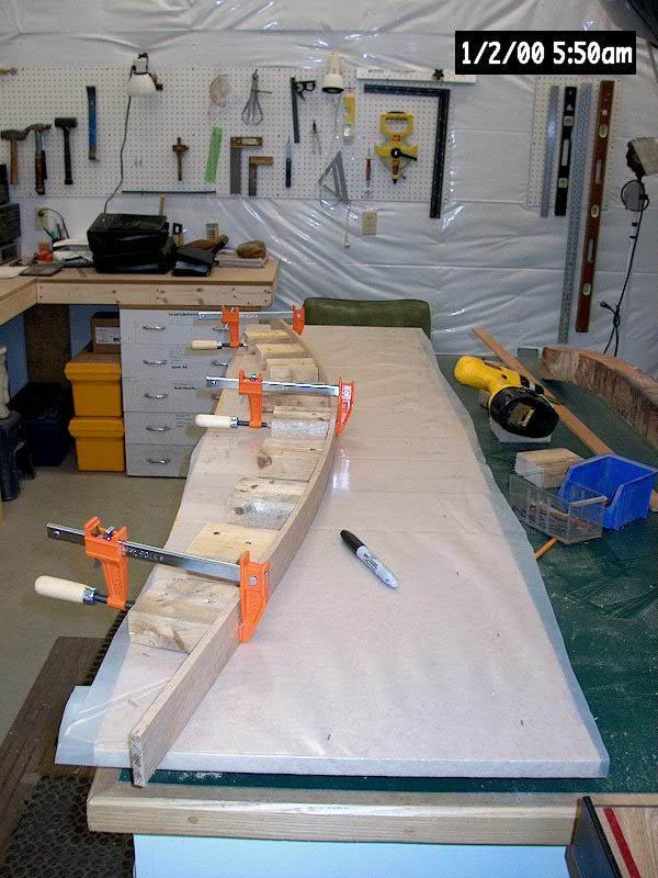
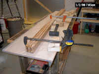
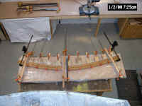
 Not
wanting any unpleasant surprises while the wood strips were covered in
gooey epoxy, I decided to perform a dry run of the lamination to see if
any issues arose. I clamped all eight strips securely on the
centerline, and began pulling them in towards the mold on each side.
I found that it was helpful to place a squeeze clamp (such as a Quick
Grip) at the end location and pull the plies in from the end, clamping the
sections closer to the centerline as I went. I soon realized that I
would need some sort of hold-down clamping setup to keep the plies in
line, as they tended to slip in a vertical direction even with no epoxy in
place yet. To that end, I clamped a couple scraps of wood across the
plies and pulled them tightly down, which nicely aligned the plies.
This was the sort of issue I had hoped to uncover during the dry fit. Not
wanting any unpleasant surprises while the wood strips were covered in
gooey epoxy, I decided to perform a dry run of the lamination to see if
any issues arose. I clamped all eight strips securely on the
centerline, and began pulling them in towards the mold on each side.
I found that it was helpful to place a squeeze clamp (such as a Quick
Grip) at the end location and pull the plies in from the end, clamping the
sections closer to the centerline as I went. I soon realized that I
would need some sort of hold-down clamping setup to keep the plies in
line, as they tended to slip in a vertical direction even with no epoxy in
place yet. To that end, I clamped a couple scraps of wood across the
plies and pulled them tightly down, which nicely aligned the plies.
This was the sort of issue I had hoped to uncover during the dry fit.
Another problem that
surfaced was that, when placed under clamping pressure, one or two of the
2x4s split around the screw holes--a common problem with junk timber,
especially older ones that were dry. It was a snap to replace the
broken ones, but I was glad to have discovered the weakness before the
actual glueup.
|
|
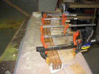
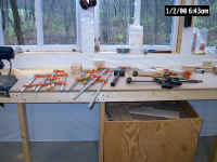 Happy
that it looked like all was going to work fine, I unclamped the dry-fit
beam and made final preparations for the actual glue-up. I covered
one of my benches in spare plastic, so that I could keep the surface clean
while wetting out and spreading the epoxy on the wood plies, and laid out
my clamps and other equipment near the mold location on the other
free-standing bench. I gathered extra clamps and set them nearby,
just in case, and collected spare pieces of plastic and scrap wood, along
with my deadblow mallet, trying to prepare for any contingency.
While there is always more time than expected to work with the epoxy when
used in this sort of method, I wanted to take no chances. Happy
that it looked like all was going to work fine, I unclamped the dry-fit
beam and made final preparations for the actual glue-up. I covered
one of my benches in spare plastic, so that I could keep the surface clean
while wetting out and spreading the epoxy on the wood plies, and laid out
my clamps and other equipment near the mold location on the other
free-standing bench. I gathered extra clamps and set them nearby,
just in case, and collected spare pieces of plastic and scrap wood, along
with my deadblow mallet, trying to prepare for any contingency.
While there is always more time than expected to work with the epoxy when
used in this sort of method, I wanted to take no chances.
|
|
 After
laying out the eight plies in the order I wanted them (I chose a smooth,
nice face for the ply that would end up forming the bottom--and most
visible--portion of the new beam), the first step was to wet out one side
of each ply with unthickened epoxy. The purpose of this was to
ensure that all areas of every bonding surface would be coated with epoxy,
but without creating excess waste from the inevitable squeeze out. I
spread the epoxy on the upturned side of each ply, ensuring that they were
evenly wet out. After
laying out the eight plies in the order I wanted them (I chose a smooth,
nice face for the ply that would end up forming the bottom--and most
visible--portion of the new beam), the first step was to wet out one side
of each ply with unthickened epoxy. The purpose of this was to
ensure that all areas of every bonding surface would be coated with epoxy,
but without creating excess waste from the inevitable squeeze out. I
spread the epoxy on the upturned side of each ply, ensuring that they were
evenly wet out.
|
|
With that step complete, I took one last look
around to ensure I was ready for the main lamination, and went ahead and
mixed up a batch of epoxy resin thickened to an adhesive texture with
cabosil. I left the mix quite loose to allow it to spread easily and
flow well once pressure was applied during clamping. The idea in
laminated glue-ups is to provide an even, consistent layer of adhesive
between each strip, without squeezing out all the glue and without
creating thick pockets of adhesive that are difficult to even out under
pressure. I thought I mixed more than enough, but of course halfway
through the process I ran out and had to mix up another batch.
Beginning with the lowest layer, I spread the adhesive on, then stacked
the next ply on top--with the resin-wetted side facing the just-applied
thickened epoxy--and then repeated the process till all eight boards were
stacked on the bench, oozing epoxy.
|
|
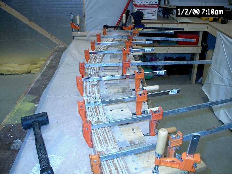
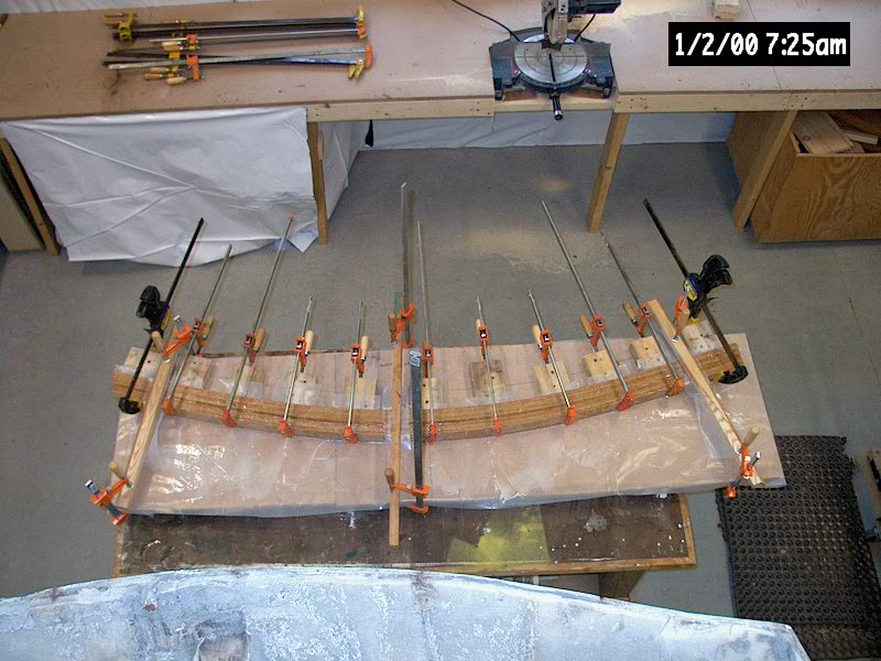
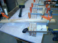
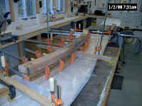
 Then,
I picked up the stack and placed it on the mold, aligning the ends of the
boards and lining the centerline up with the marked line on the
mold. I installed one clamp in the center, fairly tightly, and then
placed one of my squeeze clamps at each end to begin pulling the plies
into the mold. I drew it in a bit, then installed more clamps from
the center outward towards the end, gradually pulling the whole mess is
towards the mold blocks. I didn't worry at this stage about
unevenness in the top edges of the boards; I'd take care of that later. Then,
I picked up the stack and placed it on the mold, aligning the ends of the
boards and lining the centerline up with the marked line on the
mold. I installed one clamp in the center, fairly tightly, and then
placed one of my squeeze clamps at each end to begin pulling the plies
into the mold. I drew it in a bit, then installed more clamps from
the center outward towards the end, gradually pulling the whole mess is
towards the mold blocks. I didn't worry at this stage about
unevenness in the top edges of the boards; I'd take care of that later.
|
|
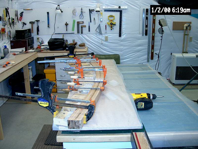
 Once
all the main clamps were on, I used my deadblow to roughly even out
the tops of the strips--wearing safety glasses in case the hammer blows
splattered epoxy spillout everywhere. Then, when I was satisfied
with the pressure on all the clamps, I installed a pair of hold-downs, one
at each end, which I had practiced with during the dry fit. Each was
made from a piece of scrap ash, which I rested on top of the laminated
plies with a piece of plastic to prevent epoxy adhesion, and I installed a
clamp on each end to pull the scraps down, which had the effect of evening
out the plies. Once
all the main clamps were on, I used my deadblow to roughly even out
the tops of the strips--wearing safety glasses in case the hammer blows
splattered epoxy spillout everywhere. Then, when I was satisfied
with the pressure on all the clamps, I installed a pair of hold-downs, one
at each end, which I had practiced with during the dry fit. Each was
made from a piece of scrap ash, which I rested on top of the laminated
plies with a piece of plastic to prevent epoxy adhesion, and I installed a
clamp on each end to pull the scraps down, which had the effect of evening
out the plies.
|
|
|
|
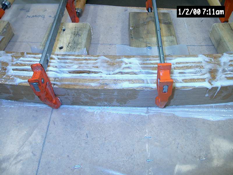
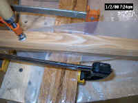
 I
spent some time ensuring that all the clamps were properly situated, and
added a third flattening clamp setup on the centerline, where there was
some tendency for the beam to spring up. Then I used a plastic
squeeze to clean up as much of the squeezeout from the top of the beam and
around the edges as possible, to make sanding and surfacing easier later
(cured epoxy and cabosil makes for very difficult sanding). Then,
just to be sure, I laid the old beam on top of the clamps and compared the
curves. I had done this several times earlier in the process, of
course, but it never hurts to check again. The curves matched
closely, allowing for the additional 1/4" of height on the new beam
to account for springback. I
spent some time ensuring that all the clamps were properly situated, and
added a third flattening clamp setup on the centerline, where there was
some tendency for the beam to spring up. Then I used a plastic
squeeze to clean up as much of the squeezeout from the top of the beam and
around the edges as possible, to make sanding and surfacing easier later
(cured epoxy and cabosil makes for very difficult sanding). Then,
just to be sure, I laid the old beam on top of the clamps and compared the
curves. I had done this several times earlier in the process, of
course, but it never hurts to check again. The curves matched
closely, allowing for the additional 1/4" of height on the new beam
to account for springback.
|
|

|
|
|
|
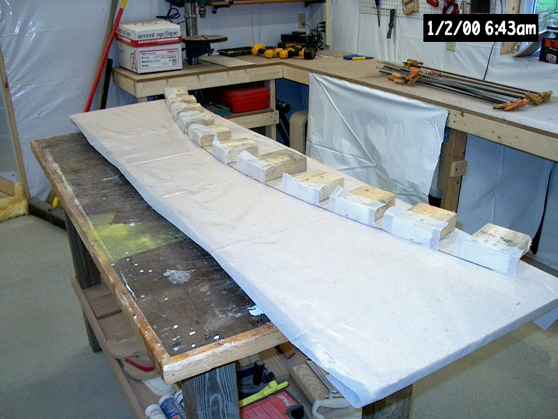
 I
left the beam to sit in the mold and clamps
for nearly 36 hours, to ensure that the epoxy would reach an advanced stage
of cure, before continuing. Then, I unclamped it and, with a small
amount of effort, broke it free from the plastic-covered mold. It
took some minor persuasion in one or two spots where the epoxy had oozed
out more heavily, but in moments it snapped free, leaving behind a nearly
clean mold ready for another use, which I shortly put to work: using
the same techniques described above, I laminated up the smaller forward
section of the beam, using the offcuts of the same material. I left
the new piece to cure in the mold for a day or two, and turned my
attention once more to the large beam. I
left the beam to sit in the mold and clamps
for nearly 36 hours, to ensure that the epoxy would reach an advanced stage
of cure, before continuing. Then, I unclamped it and, with a small
amount of effort, broke it free from the plastic-covered mold. It
took some minor persuasion in one or two spots where the epoxy had oozed
out more heavily, but in moments it snapped free, leaving behind a nearly
clean mold ready for another use, which I shortly put to work: using
the same techniques described above, I laminated up the smaller forward
section of the beam, using the offcuts of the same material. I left
the new piece to cure in the mold for a day or two, and turned my
attention once more to the large beam.
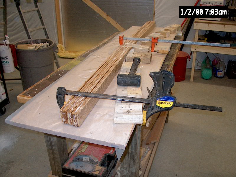
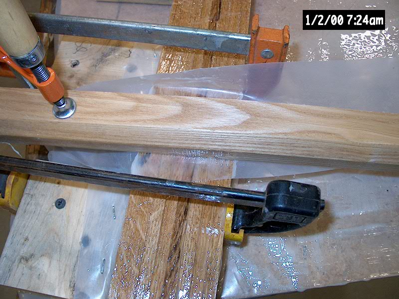
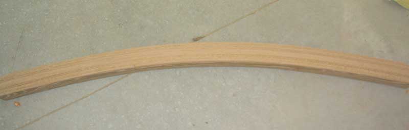
The surface of the beam
that had been facing upward was relatively free of epoxy, but there was
some slight unevenness in the plies. The other side, the one that
had been firmly pressed into the plastic, was covered with a thin, smooth,
even layer of epoxy spillout, with additional minor unevenness to match
the other side. The beam overall was straight, true, and free from
twists or other problems--not that I was worried, but it was still nice to
see a new project turn out as expected. Springback was minimal when
I unclamped the piece--perhaps 1/8", but certainly less than the
projected 1/4". I was very pleased with the result.
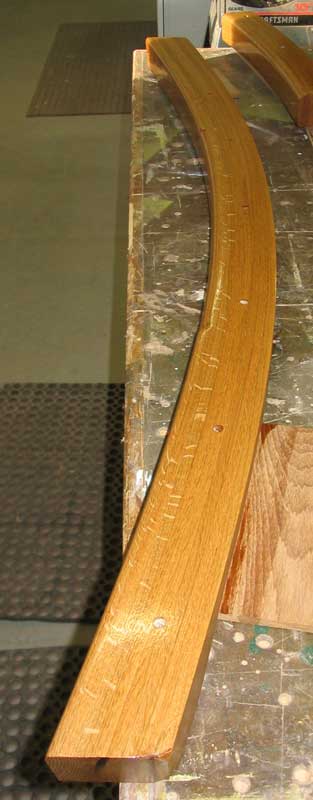
My next step was to remove
the thick globs of hardened epoxy from the edges, and then to sand the
beam smooth, particularly on the aft-facing side, which was to be
varnished and exposed in the cabin. The forward side would be
invisible, so all I had to do was smooth it to ensure it was flat and
even. To
clean up the beam, I briefly considered trying to run the whole thing
through the planer, but decided that it was prudent to at least try
sanding first, lest I ruin the beam, the planer knives, or both in the
process. To sand the beam, I used a belt sander with 60 grit paper,
running the sander perpendicularly across the plies to even out any
irregularities and to remove excess epoxy. Once the whole face was
smooth, I ran the sander with the grain to remove cross-grain marks caused
by the flattening process. Then, I used a DA sander to sand the top
and bottom edges of the arc, just enough to remove the epoxy oozeout and
handprints. The sanding wasn't particularly difficult at all, and
did a fine job cleaning up the beam. More final sanding will occur
later in the process before the beam is varnished and installed for good.
|
|
Next, I began the process of sizing and
fitting the beam. First, I laid the old beam on top, and marked the
ends on the new beam. Then, to double check how the old beam fit, I
took it up to the boat and put it in place, and noted that it didn't
extend all the way to the sides of the cabin. Therefore, I decided
to cut the new beam slightly longer, which would not only give me a fudge
factor for the final fitting, but also might allow me to run the beam all
the way to the edges. With my checking and double checking done, I
cut the new beam roughly to length on the chop saw. The clean cut
highlighted the even, thin 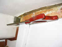 glue lines between the plies, indicating that
the clamping pressure appeared to have been even and appropriate. glue lines between the plies, indicating that
the clamping pressure appeared to have been even and appropriate.
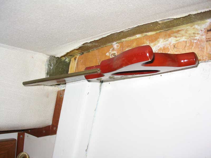
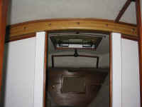
With the beam cut to
length, I tried fitting it in place. Because of a slightly different
arc built into the new beam, I found I had to remove a small amount of
material from each of the two vertical support posts on the port side so
that the new beam could slide over the top. I cut these with a hand
saw, which was made overly difficult and time-consuming because of the
fine teeth on the one decent backsaw I had.
|
|
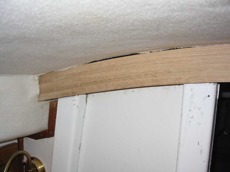
My first attempt at a dry
fit revealed that I had to cut the ends at a slight angle relative to the
face of the beam, to accommodate the fact that the cabin trunk narrows as
it runs forward. A compound miter box would have been nice, but
since I don't have one, I worked out a way to use my fixed miter box to
make the cuts at the appropriate angle (about 11.5 degrees). After a
few more trial fits and slight modifications to the ends and the top
surface of the beam (slight stock removal in a few areas necessary), the
beam slid tightly into place--just the fit I wanted. I still needed
some minor persuasion to get the beam snugly into its home, but it wasn't
so tight that it was being forced.
|
|
|
|
 With
the beam fit in place, I marked the extent of the opening in the bulkhead
on the forward side of the beam, and prepared to cut the smaller laminated
sub-beam to fit. After measuring, cutting overly long on purpose,
and some additional trial fitting, I had the second beam section properly
sized. I discovered that, because of the forward-sloping top of the
coachroof, the small beam section protruded below the main beam by
1/4" or so--had I though it through, I could have simply eliminated 1
or 2 of the laminations during the build process. Now, however, I
needed a way to trim the bottom of the small beam down to
size. With
the beam fit in place, I marked the extent of the opening in the bulkhead
on the forward side of the beam, and prepared to cut the smaller laminated
sub-beam to fit. After measuring, cutting overly long on purpose,
and some additional trial fitting, I had the second beam section properly
sized. I discovered that, because of the forward-sloping top of the
coachroof, the small beam section protruded below the main beam by
1/4" or so--had I though it through, I could have simply eliminated 1
or 2 of the laminations during the build process. Now, however, I
needed a way to trim the bottom of the small beam down to
size.
At first, I thought I would
try to make the small beam flush with the main beam. Since I don't
have a bandsaw, my tool of choice was my portable jigsaw.
Unfortunately, the saw made a terrible cut because of blade wander through
the thick, dense material. While the visible cutline on top of the
beam seemed OK while I was making it, when I finished I realized that the
cut was completely unacceptable: wavy, uneven, and just awful.
I put the piece aside for the night while I thought about other courses of
action.
In the end, I decided to
use my belt sander to remove the material necessary, since none of the
saws I had were up to the task. Using the main beam as a guide, I
marked a smooth arc on each side of the small beam with a pencil, clamped
the beam upside down in a Workmate, and fired up the belt sander.
The coarsest sanding belt I had was 80 grit, and I went through three
belts as I removed nearly 1/4" of white oak. It only took about
10 minutes, and I was pleased with the end result. Since a flush fit
was impossible (after my botched initial cut), I chose to recess the
forward piece by about 1/4".
|
|
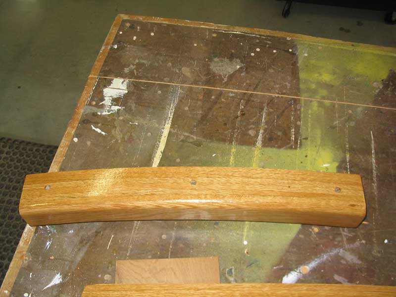
With that done, and a final
trial fit, the beams were complete. I removed both pieces and
performed some finish milling. I routed a 3/4" roundover in the
area where the beams span the passageway, and a 1/4" roundover on the
remaining edge of the main beam, and then sanded both sections smooth
through 220 grit. The beams cleaned up extremely well, and the
large-radius rounded edges just screamed out to be touched.
I applied
a coat of sealer varnish (50% varnish, 50% thinner) to the beams to
prevent any staining or discoloration before continuing with the final
fitting.
I
decided to emulate the original installation technique, which had
certainly seemed adequately strong and suitable for the task. The
original beams were bolted through the main bulkhead and to each other,
and featured no other means of attachment except for some lightweight
tabbing at the beam ends. The load from the mast is transferred
directly downwards through the beam arch and into the compression posts
secured to the bulkhead, with some load transfer also occurring through
the bolts and into the bulkhead.
I
ordered some 5/16" silicon bronze carriage bolts from Jamestown
(expensive!) in two lengths--one set for bolting the main beam to the
bulkhead (3-1/2"), and some longer ones for bolting the two sections
of beam together in the center (4-1/2"). I went with bronze for
strength, longevity, and, mostly, looks, since the bolts would be visible
in the final product.
 With
the beams in place, I marked exactly where the forward section of beam
fell against the main beam, and then removed both sections one last
time. The marks were important because I needed to mock up the setup
on the bench so that I could drill holes for the bolts, and so that the
boltholes could be located in an aesthetically pleasing manner. With
the beams in place, I marked exactly where the forward section of beam
fell against the main beam, and then removed both sections one last
time. The marks were important because I needed to mock up the setup
on the bench so that I could drill holes for the bolts, and so that the
boltholes could be located in an aesthetically pleasing manner.
I
marked for three holes towards the center of the beam, evenly spaced
through the smaller forward beam section, and four additional holes--two
per side--for attaching the main beam to the bulkhead. Then, I
drilled all 7 holes with a 21/64" bit on my drill press.
With
the holes drilled, I lightly sanded the beams and applied the first of
several more coats of varnish before installing the beams in the boat.
I finished up with a coat of a floor polyurethane, with a satin sheen
finish, that looks simply awesome on oak.
|
|

|
|
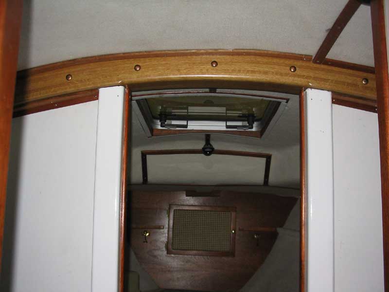
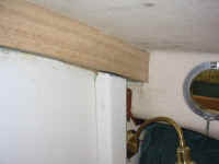
 When
the varnish was complete, I
installed the beam in the boat. To secure it, I used silicone bronze
carriage bolts through the main bulkhead, with the rounded heads facing
the (suitably) head, and the nuts and washers in the forward cabin.
I attached the sistered forward portion of the beam with three similar,
though longer, bolts. I decided that the bolts were more than
sufficient to secure the beam. Fortunately, the new beam fit closely
enough to the overhead, especially in the crucial center span beneath the
mast step, that no further reinforcement was needed. When
the varnish was complete, I
installed the beam in the boat. To secure it, I used silicone bronze
carriage bolts through the main bulkhead, with the rounded heads facing
the (suitably) head, and the nuts and washers in the forward cabin.
I attached the sistered forward portion of the beam with three similar,
though longer, bolts. I decided that the bolts were more than
sufficient to secure the beam. Fortunately, the new beam fit closely
enough to the overhead, especially in the crucial center span beneath the
mast step, that no further reinforcement was needed.
|
|
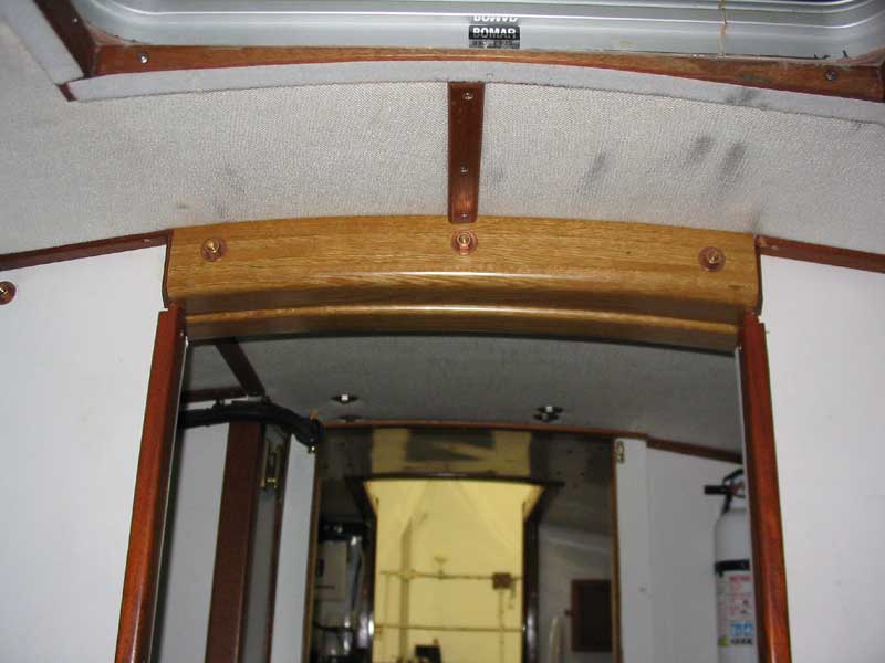
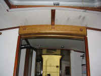 I
trimmed out the edges of the mast beam with narrow mahogany strips, many
of which I had used in the original setup. I also had to cut a few
new pieces of trim here and there to replace some of the old pieces that
didn't fit properly anymore. I
trimmed out the edges of the mast beam with narrow mahogany strips, many
of which I had used in the original setup. I also had to cut a few
new pieces of trim here and there to replace some of the old pieces that
didn't fit properly anymore.
The mast beam replacement
was complete!
|
|